Scott Wurcer, you wrote:
"I just confirmed that with an ordinary TEF the tuning of the drop in the degeneration resistors is totally messed up by having a phase to the load. I tried 5.7 Ohms and .9mH for a mag of 8 ohms at 45 degrees. Tuned to .009% degraded to .03%. Actually if you take just the thirds..."
in another place, where registration is impossible.
I confirm your findings. I am doing similar simulations, and later would make some measurements with dummy speaker load.
Hello Pavel
Can you give the link of the complete Scott Wurcer post ?
I'm interest to read it.
Thank you
Bye
Gaetan
Can you give the link of the complete Scott Wurcer post ?
I'm interest to read it.
Thank you
Bye
Gaetan
Last edited:
Scott Wurcer, you wrote:
"I just confirmed that with an ordinary TEF the tuning of the drop in the degeneration resistors is totally messed up by having a phase to the load. I tried 5.7 Ohms and .9mH for a mag of 8 ohms at 45 degrees. Tuned to .009% degraded to .03%. Actually if you take just the thirds..."
in another place, where registration is impossible.
I confirm your findings. I am doing similar simulations, and later would make some measurements with dummy speaker load.
I did some sims using these load values.
Results are quite unexpected.
Conditions were : 10 KHZ 40V PP 8R and 5.6R + 0.91mH
The amplifier is a symetrical differential with no extraordinary
open loop gain and gainbandwith perfs, as it was designed for stability.
With pure resistive load, distorsion in a 1MHZ bandwith is 0.075%
Using the reactive load, the numbers collapsed to 0.0001% with
all high order harmonics vanishingly low.
I ll recheck all this a bit deeper.
I knew that reactive loads modify the distorsion s profiles, but not
to this extent..
Why did you not include the first sentence of what he wrote?
I was thankful that someone put together a sim that actually showed these effects. Frankly the circuits and models changed so often I didn't have the time to sort this out (some sets showed nothing). I will repeat this exercise was useful in that I had never thought of the effects of load phase on EF's. So I will repeat. The Early voltage modulation of Vbe is in phase with the output voltage and the Vbe modulation with current is is in phase with the current. They are both sources of distortion.
There was nothing there that would offend anyone.
Last edited:
I did some sims using these load values.
Results are quite unexpected.
Conditions were : 10 KHZ 40V PP 8R and 5.6R + 0.91mH
The amplifier is a symetrical differential with no extraordinary
open loop gain and gainbandwith perfs, as it was designed for stability.
With pure resistive load, distorsion in a 1MHZ bandwith is 0.075%
Using the reactive load, the numbers collapsed to 0.0001% with
all high order harmonics vanishingly low.
I ll recheck all this a bit deeper.
I knew that reactive loads modify the distorsion s profiles, but not
to this extent..
Hum..A sim issue..silly me!!
I did average over 200 cycles and the numbers are less distant..
0.0173% with resistive load and 0.00398 with complex load.
A 12db ratio, somewhat more realist..
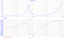
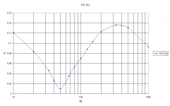
PMA's plots show some interesting facts.
The load hits 4ohm 50degree phase angle at ~19Hz and ~130Hz.
At both these frequencies the distortion is neither at minima nor maxima.
At 50Hz the load phase angle is zero degrees and the resistive impedance is 24r
The distortion is at minimum driving this frequency. To be expected, with a resistive low current load.
The other zero phase angle frequency (330Hz) throws up an anomaly. Here the resistive load is ~2r0.
The distortion is near maxima into this resistive high current load. Why?
Why does the distortion appear to fall from this resistive maxima to the more reactive loading above 400Hz?
Referring back to the 50Hz distortion. Why is it appearing so much better than the 1kHz distortion? Has this amplifier been accidentally optimised for minimum distortion at low frequencies and low currents?
Seems that distorsion is inversely proportionnal
to the impedance.
I guess that a resistive load varying the same way
with frequency would yield about the same figures,
apart from a slight reduction in the distorsion delta.
A comparison with a resistive load would be insightful.
to the impedance.
I guess that a resistive load varying the same way
with frequency would yield about the same figures,
apart from a slight reduction in the distorsion delta.
A comparison with a resistive load would be insightful.
Referring back to the 50Hz distortion. Why is it appearing so much better than the 1kHz distortion? Has this amplifier been accidentally optimised for minimum distortion at low frequencies and low currents?
There s surely a bit more NGFB at 50hz.
[snip]Referring back to the 50Hz distortion. Why is it appearing so much better than the 1kHz distortion? Has this amplifier been accidentally optimised for minimum distortion at low frequencies and low currents?
Most of the time, when you see something like this, it shows hum that is in opposite phase to the distortion so it largely cancels.
I normally just disregards it as THD below 1kHz is almost always flat, except when you use a cap in the fb loop.
jd
There was nothing there that would offend anyone.
Correct. I was not offended in any way. I think it is good to follow this path of investigation.
gaetan8888;
Here is the link to the post on the other site.
Bias point with "real" loads?
And here is a link to where he began to discuss on in this site.
http://www.diyaudio.com/forums/solid-state/151295-krill-next-generation-22.html#post2087722
Thanks, Steve. Let's stay cool here.
Anyone with his results, simulated or measured welcome.
Regards,
Anyone with his results, simulated or measured welcome.
Regards,
I agree that a "standard" load should be used as a reference point. The Stereophile simulated speaker load is slightly different from the one I have been using, but I don't mind changing to that one so we all work with the same load.
Some 5 years ago I built very similar load as Stereophile. The biggest problem is to use it at high power. Big chokes are on ferrite core, and saturate at low power.
Correct. I was not offended in any way. I think it is good to follow this path of investigation.
gaetan8888;
Here is the link to the post on the other site.
Bias point with "real" loads?
And here is a link to where he began to discuss on in this site.
http://www.diyaudio.com/forums/solid-state/151295-krill-next-generation-22.html#post2087722
Hello Steve
Thank for the link.
Myself, to sim close to a real load, I use this loudspeaker model that I've found at this link.
http://www.diyaudio.com/forums/atta...773d1120366791-many-faces-distortion-ldc6.pdf
Bye
Gaetan
- Status
- Not open for further replies.
- Home
- Amplifiers
- Solid State
- Distortion with "real" loads