Hi,
as my minidsp seems to increase the noise considerably and I usually try to keep it simple,
I plan to make a PCB for a relatively basic 2-way crossover.
As nice as it is playing with configurations I doubt the minidsp doesn´t influence the signal in some way.
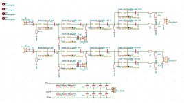
Idea is to have the same buffer-schematic for most stages, except input-buffer and line-out/headphone-out (which are without most of the passive elements)
It is laid out so one can make a 12dB-HP/LP, high shelf-, low-shelf-filter per block (or combine within the block).
The schematic for the buffer show resistors to the left of the buffer which really should be read as "Z" and thus R,C or L.
Footprint is 1210 and so it can take R&C of various footprints (1206 and even some 0805). Everything will be handsoldered.
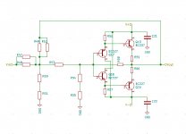
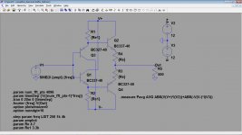
The used diamond buffer is really the simplest version of them all but seems to simulate well enough, even down to typical headphone-loads.
DC-offset seems low enough that only at the in- and output of the whole circuit a capacitor would be needed.
Power will be supplied with a Jung/Didden-super-regulator from the DIYaudio-store.
If you see any errors or have any comments you´re welcome!
Thanks & best regards
Jens
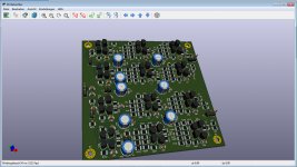
PS.: I used the "replicate layout"-plugin from Kicad and it works really well (if you refine hierarchical sheet´s layout and don´t have any errors🙄)
as my minidsp seems to increase the noise considerably and I usually try to keep it simple,
I plan to make a PCB for a relatively basic 2-way crossover.
As nice as it is playing with configurations I doubt the minidsp doesn´t influence the signal in some way.
Idea is to have the same buffer-schematic for most stages, except input-buffer and line-out/headphone-out (which are without most of the passive elements)
It is laid out so one can make a 12dB-HP/LP, high shelf-, low-shelf-filter per block (or combine within the block).
The schematic for the buffer show resistors to the left of the buffer which really should be read as "Z" and thus R,C or L.
Footprint is 1210 and so it can take R&C of various footprints (1206 and even some 0805). Everything will be handsoldered.
The used diamond buffer is really the simplest version of them all but seems to simulate well enough, even down to typical headphone-loads.
DC-offset seems low enough that only at the in- and output of the whole circuit a capacitor would be needed.
Power will be supplied with a Jung/Didden-super-regulator from the DIYaudio-store.
If you see any errors or have any comments you´re welcome!
Thanks & best regards
Jens
PS.: I used the "replicate layout"-plugin from Kicad and it works really well (if you refine hierarchical sheet´s layout and don´t have any errors🙄)
Attachments
Last edited:
