I have been working on rebuilding and upgrading a Threshold 400a amplifier and have determined nearly all components necessary for the final rebuild. I have analyzed and mapped the existing original circuit and have found some differences from all schematics that I have seen. I am wanting to upgrade the amp during the rebuild to ensure and hopefully increase stability and performance. There are just a couple of areas that I am not fully comprehending and wonder if anyone else out there can enlighten me. I will attach a layout of the schematic as the actual physical circuit currently stands. The schematic has all components numbered for reference. I will also include pics of the few main components of interest.
First question is that this circuit has a resistor UR2 (left side of schematic) attached to the underside of the board that provides a bypass around the D5 diode at the base-emitter of transistor T9. I cannot understand why this bypass resistor is used at the input pair. I am thinking this negates the effectiveness of the D5 diode. The only potential reason I can think of for this resistor is to possibly help balance the T9 transistor with T10 if the pair were not closely enough matched to start. Anyone know why this resistor is used or there?
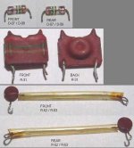
Second question is that the bias circuit is somewhat different than I have seen in any of the other schematics or Pass designs. Between the emitter junctions of transistors T3a and T4a there appear to be two diodes D7 and D8 (central area of schematic) that have been included in this design. I’m not understanding why these diodes have been included in this particular position between the two transistors in this manner. The diodes are marked with “ITT” and Brown/Green/Brown stripes that would indicate a 1N151 diode. I have researched this diode and it appears to be a Silicon Rectifier Germanium Diode. I think I may have seen Mr. Pass call specifically for a Germanium Diode in other designs so I am thinking these two diodes may have been included for some specific properties related with germanium that I am not aware of. One of the diodes is damaged and requires replacement and I would want to upgrade to a modern equivalent form digikey but do not want to make a decision without understanding if there is some specific property I need to be looking for. Also, the resistor R31 tying these transistors to the main line is showing only 10 ohm while all other schematics are indicating a 10k resistor. The resistor bands decode to indicate a 250 ohm resistance (red/green/brown) so I am a bit perplexed at the differences of this area of the bias circuit when compared with the other typical 400a schematics I have seen. Since I want to ensure and increase stability this bias area is pretty important to get straight. Anyone know why the diodes have been introduced and included in this version and if germanium is an important factor for some reason in this application?
Lastly, there are two thyristors R-52 and R-53 that have no markings on them. Anyone know what the specs are for these guys?
Thanks for any input…
First question is that this circuit has a resistor UR2 (left side of schematic) attached to the underside of the board that provides a bypass around the D5 diode at the base-emitter of transistor T9. I cannot understand why this bypass resistor is used at the input pair. I am thinking this negates the effectiveness of the D5 diode. The only potential reason I can think of for this resistor is to possibly help balance the T9 transistor with T10 if the pair were not closely enough matched to start. Anyone know why this resistor is used or there?
Second question is that the bias circuit is somewhat different than I have seen in any of the other schematics or Pass designs. Between the emitter junctions of transistors T3a and T4a there appear to be two diodes D7 and D8 (central area of schematic) that have been included in this design. I’m not understanding why these diodes have been included in this particular position between the two transistors in this manner. The diodes are marked with “ITT” and Brown/Green/Brown stripes that would indicate a 1N151 diode. I have researched this diode and it appears to be a Silicon Rectifier Germanium Diode. I think I may have seen Mr. Pass call specifically for a Germanium Diode in other designs so I am thinking these two diodes may have been included for some specific properties related with germanium that I am not aware of. One of the diodes is damaged and requires replacement and I would want to upgrade to a modern equivalent form digikey but do not want to make a decision without understanding if there is some specific property I need to be looking for. Also, the resistor R31 tying these transistors to the main line is showing only 10 ohm while all other schematics are indicating a 10k resistor. The resistor bands decode to indicate a 250 ohm resistance (red/green/brown) so I am a bit perplexed at the differences of this area of the bias circuit when compared with the other typical 400a schematics I have seen. Since I want to ensure and increase stability this bias area is pretty important to get straight. Anyone know why the diodes have been introduced and included in this version and if germanium is an important factor for some reason in this application?
Lastly, there are two thyristors R-52 and R-53 that have no markings on them. Anyone know what the specs are for these guys?
Thanks for any input…
Attachments

There are several variations of the 400A, and not all schematics
I've seen are correct.
The UR2 reference is an optional trim resistor for DC offset
adjustment. It is not essential, and the offset can be trimmed
elsewhere. It is not on my copy of the schematic.
The Germanium diodes were chosen for the forward voltage
characteristic of Germanium to set the where we wanted it.
Any generic Germanium replacement (signal) diodes will do fine.
I don't recall the specific value of R31, but the higher the value,
the less the gain of the bias circuit. My schematic shows
twin 10K ohm values, but I recall lesser values also, depending
on the values in the rest of the network.
R52 and R53 are thermistors, whose value declines with
temperature, and they are mounted on the output stage for
temperature compensation. I don't recall their values, and
again, they aren't on my schematic, but we usually used 1K
ohms (room temp) values for thermistors.
- Status
- Not open for further replies.