Wondering why the use of L78XX/L79XX with current boost(MJ2955/2N3055) is not popular as a simple linear regulator for chip amps and such?
Circuits like this (showing positive rail)
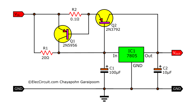
What are the reasons to shun these? Bad line/load regulation? Efficiency? For example a 15-0-15 200VA with the above configuration can make a good +/-18 V 5A power supply in theory.
I understand Opamp based finer designs with precise reference voltages have better line and load regulation. Is that the only reason?
Circuits like this (showing positive rail)
What are the reasons to shun these? Bad line/load regulation? Efficiency? For example a 15-0-15 200VA with the above configuration can make a good +/-18 V 5A power supply in theory.
I understand Opamp based finer designs with precise reference voltages have better line and load regulation. Is that the only reason?
Mission use a variant of this circuit in their PSX-R regulated supples. Based on a 317/337 indeed as these are considerably better than the fixed types, but same concept. And apparently with a considerable success. There is no easier way to obtain a high current regulated supply that is also reasonably good sounding than this.
Because they are very noisy and quite slow (cannot respond adequately to a fast transient current change). The new generations of TO220 regs from LT et al are much faster, quieter and many are designed to be paralleled simply for higher output currents.
And I am not sure how your example in your post gets from 12Vin to 15Vout (presume its a typo)
And I am not sure how your example in your post gets from 12Vin to 15Vout (presume its a typo)
You need a 15V regulator for that
The current limiting has longer recovery time which is not so good for audio. Usually the limit is already done in the output stage
R2 increases the interior resistance
Usually amplifiers do not require a strictly regulated voltage, you throw away some headroom
The current limiting has longer recovery time which is not so good for audio. Usually the limit is already done in the output stage
R2 increases the interior resistance
Usually amplifiers do not require a strictly regulated voltage, you throw away some headroom
Last edited:
Because they are very noisy and quite slow (cannot respond adequately to a fast transient current change). The new generations of TO220 regs from LT et al are much faster, quieter and many are designed to be paralleled simply for higher output currents.
And I am not sure how your example in your post gets from 12Vin to 15Vout (presume its a typo)
That circuit is just a reference on topology please ignore the values shown in the circuit. Actual circuit will be with double rails and 7918 and 2N3055 on the negative rail.
15-0-15 center tapped transformer can do this as a +/- Vin as after rectification the Vdc will be around 21v.
Nothing inherently wrong, and I've seen it used to power things like small mixing consoles where a regular 7815 / 7915 isn't enough.
It is relatively uncommon (and generally not necessary) to use a regulated power supply for a power amplifier though. Most circuits have decent PSRR and a lot of regulators have poor transient response. A regulated PS with poor transient response will usually perform much worse than an unregulated PS with adequate capacitance, at least for a power amplifier.
It is relatively uncommon (and generally not necessary) to use a regulated power supply for a power amplifier though. Most circuits have decent PSRR and a lot of regulators have poor transient response. A regulated PS with poor transient response will usually perform much worse than an unregulated PS with adequate capacitance, at least for a power amplifier.
Having some amount of smoothing/reservoir caps after the regulator a bad choice? Something like 15-0-15 (2.8A) transformer, then 10000μF per rail reservoir caps, then the above regulator stage, followed by 6800μF per rail caps before the load. Wouldn't that take care of some of the transient response problem?
Sure, but at that point you have to ask yourself why you'd even bother to regulate it. If it's to kill ripple / noise, then a capacitance multiplier is a better choice.
Truth is, most of this stuff really doesn't need exact power supply voltages.
Truth is, most of this stuff really doesn't need exact power supply voltages.
And, a bit more support for the idea:
When you feel that you need an ordinary quality regulated voltage with high current capability, this is a good choice. LT can no doubt do better but then you have to pay more to get those.
Many applications do not benefit from better voltage regulation performance than what you suggest and you probably have those parts already. Personally I prefer an NPN buffer transistor to a PNP buffer transistor if the load has a very dynamic consumption.
In professional production, one single LT device may be cheaper to handle. It is not that I discard LT but for DIY-hobbyists the situation is different. And you easily make negative versions.
Neither 78xx, nor LM317 are particularly high performance (noise, load regulation etc.), but good enough for most use.
Last edited:
OP's circuit works really well for a small DIY bench supply; when properly-implemented the power transistor can stand-off the excess voltage, and deal with the resulting thermal dissipation, that LM108x types cannot. Suppose you want 3A+ at lower voltage, from a 20v or more raw supply: the TO220 regs go into thermal-limiting very early...
I've no opinion on the suitability as an amplifier PSU - I prefer to ensure my amplifiers have great intrinsic PSRR first.
There is no reason this 'regulator with external pass transistor' cannot be made to work well though: just keep any output bypass capacitance moderate, and - more importantly as close as possible to the circuit it serves ( bypassing the load, not the regulator !)
(- The regulator (assuming LM3x7 etc) does not need any bypass capacitance at the regulator's output for stability.)
Last edited:
...
that said
I'd not use a regulator, to provide power to a power amp's output stage; teh emitter-folower hage huge PSRR on its own, and inside the feedback loop, if implemented well.
Secondly - that leaves using a regulator of the input, and possibly also the VAS stage.
- For such low currents as those two stages require:there are easier, simpler, inherently-stable alternatives I'd rather go for.
See what I mean about amplifier PSRR first?
LM1083/LD1083 exists.
That's interesting. And they are linear with no ripple issues I can see.
As an experiment to those who think regulated power supplies are "better" for a power amplifier, do this:
Take a decent regulated power supply. For example, maybe take a good bench supply. I've tried this on Power One linear supplies, my Hameg HM7044 (which is equivalent to a R&S power supply now) and a few HP supplies. Use a MOSFET or an IGBT (with a series resistor) as a load. The MOSFET is a switch. Now use a signal generator to pulse the gate. Essentially what you're doing, if you implement your test well, is creating a pulsed load. Look at the output of the PS on a scope as you do this.
After you recover from the mild heart attack from seeing how slow a $1600 lab supply is, try it with an unregulated power supply with a chunky filter cap. Bonus style points if you use a squishy transformer and undersized bridge. You'll still find that it's faster, in all likelihood. Most linear regulators, as a result of their compensation, are a little slow.
An amplifier generally presents exactly this kind of load. The reason most power amps, even the most expensive ones on the market, use unregulated power supplies is that they handle transients very well.
Some amplifiers will have VERY high THD on a bench supply as a result of this. When I finish my dual adjustable 0-6A 0-70V lab supply for testing amplifiers, there will be an additional bank of 10,000 uF capacitors that can be switched in to get around this issue, because I've spent way too much time chasing performance issues on the bench that were the result of an amplifier circuit that's faster than the regulated power supply it's running from.
Last edited:
The reason most power amps, even the most expensive ones on the market, use unregulated power supplies is that they handle transients very well.
I agree. Regulation always leaves a sonic imprint, in preamps too. Some of it may be used to enhance particular sonic attributes that appeal to some listeners.
Naim, Linn, Mission, Mark Levinson have all made regulated power amps which earned deserved attention. None of them were very convincing dynamically but dynamics is not a sonic trait all listeners find desirable.
My own DIY laboratory power supply is 26V x 4 A DC, and is made with LM350 (or LM338, I don't remember now exactly) and DC-DC pre-regulator, so I understand what are you talking about. Notice: TO220 case device for 4A and about 30V raw DC input (after rectifying). I can have 1.25VDC and 4 ADC, or 26VDC and 4 ADC.. Suppose you want 3A+ at lower voltage, from a 20v or more raw supply: the TO220 regs go into thermal-limiting very early...
But here this topic is about 78xx/79xx devices that are not adjustable, so the problem you are talking about is not a much problem: you just have to properly choose input voltage (if there is a possibility). If we want to make 5VDC from 20 VDC with a large current - there we can consider different effective ways (and current boost is one of them).
Last edited:
To come back to the original question:
I simulated the circuit. Used 10A Schottky and a 22000uF reservoir.

Red Capacitor Blu current Grn output
Unfortunately the outdated semiconductors do not do well even 15V can not be reached. The 2N2955 needs Veb= -1.29V the regulator saturates at 1.68V and the 100m ohm another 0.5V with 5A load current
when the output has more than 1uF load it starts oscillating, but with 10000uF is stable again.
Used a LM317 to have adjustable output.
I simulated the circuit. Used 10A Schottky and a 22000uF reservoir.
Red Capacitor Blu current Grn output
Unfortunately the outdated semiconductors do not do well even 15V can not be reached. The 2N2955 needs Veb= -1.29V the regulator saturates at 1.68V and the 100m ohm another 0.5V with 5A load current
when the output has more than 1uF load it starts oscillating, but with 10000uF is stable again.
Used a LM317 to have adjustable output.
Last edited:
- Home
- Amplifiers
- Power Supplies
- Disadvantages of using L78XX/L79XX with current boost(MJ2955/2N3055)