All of the outputs are removed right now since some were defective..
Amp is still stuck in protection mode..
Heres what i get on the 494
Pin1:0
Pin2:4.96
Pin3:.05
Pin4:4.84
Pin5:1.46
Pin6:3.64
Pin7:0
Pin8:13.04
Pin9:0
Pin10:0
Pin11:13.04
Pin12:13.04
Pin13:4.96
Pin14:4.96
Pin15:4.96
Pin16:4.96
Amp is still stuck in protection mode..
Heres what i get on the 494
Pin1:0
Pin2:4.96
Pin3:.05
Pin4:4.84
Pin5:1.46
Pin6:3.64
Pin7:0
Pin8:13.04
Pin9:0
Pin10:0
Pin11:13.04
Pin12:13.04
Pin13:4.96
Pin14:4.96
Pin15:4.96
Pin16:4.96

Re-check the voltage on pin 16. 13, 14 and 15 may be shorted together which would account for having precisely the same voltage on those but pin 16 wouldn't be shorted to those and is unlikely to have precisely the same voltage.
Do you see a pulse of DC on the large output filter inductors as the amp tries to power up?
Is pin 4 of the 494 connected to the collector of a PNP transistor (possibly through a low value resistor)?
Is pin 4 of the 494 connected to the collector of a PNP transistor (possibly through a low value resistor)?

DC offset must be what's shutting it down.
Post the DC voltage on all of the pins of the B52 IC.
Pin 1:
Pin 2:
Pin 3:
Pin 4:
Pin 5:
Pin 6:
Pin 7:
Pin 8:
Pin 9:
Pin 10:
Pin 11:
Pin 12:
Pin 13:
Pin 14:
Post the DC voltage on all of the pins of the B52 IC.
Pin 1:
Pin 2:
Pin 3:
Pin 4:
Pin 5:
Pin 6:
Pin 7:
Pin 8:
Pin 9:
Pin 10:
Pin 11:
Pin 12:
Pin 13:
Pin 14:
Pin 1: 3.50
Pin 2: 0
Pin 3: 3.50
Pin 4: 3.50
Pin 5: 0
Pin 6: 3.50
Pin 7: 0
Pin 8: 3.42
Pin 9: 3.05
Pin 10: 3.44
Pin 11: 3.40
Pin 12: 0
Pin 13: 3.40
Pin 14:3.38
Pin 2: 0
Pin 3: 3.50
Pin 4: 3.50
Pin 5: 0
Pin 6: 3.50
Pin 7: 0
Pin 8: 3.42
Pin 9: 3.05
Pin 10: 3.44
Pin 11: 3.40
Pin 12: 0
Pin 13: 3.40
Pin 14:3.38
See if the voltages are different on the inductors and the IC If you use the secondary CT as the reference (black probe).
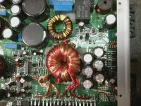
They are where the two center wires on the power transformer that go into the board near the yellow cored inductor.
I think you'll find that everything reads 0v. If that's the case, you'll have to remove the transistor that's driving pin 4 high, clamp all transistors tightly to the heatsink and power the amp up via a 15 amp fuse or a current limiter. There is some risk that the outputs will be damaged (I'm assuming that you've checked the outputs and none are defective as of now) but you need to get the amp to power up to find what's causing the fault.
I think you'll find that everything reads 0v. If that's the case, you'll have to remove the transistor that's driving pin 4 high, clamp all transistors tightly to the heatsink and power the amp up via a 15 amp fuse or a current limiter. There is some risk that the outputs will be damaged (I'm assuming that you've checked the outputs and none are defective as of now) but you need to get the amp to power up to find what's causing the fault.
if i remove the transistor that connects to pin 4 the amp wont power up and the protection light goes off..
Pin 4 of the 494 the voltages pulse's up and down with the transistor removed
Pin 4 of the 494 the voltages pulse's up and down with the transistor removed
Does the power supply stay on long enough (between pulses) to have a steady regulated voltage on the op-amps?
Ok i had the wrong transistor Pulled an A1266 (Q13) amp powers up and relays kick on. Amp idles perfectly
If it has 2 op-amps near the power supply IC, post the DC voltage on all of the pins of each one.
- Status
- Not open for further replies.
- Home
- General Interest
- Car Audio
- Directed 1500D