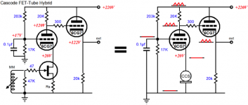
For decades (since around 1985) I have a tubes-based passive RIAA with a hybrid cascode input stage. The trick I devised then was to have a 2SK240 where the drain was connected to the cathode of the ECC88; actually the pair in the 2SK240 both parallel and a E88CC also parallel.
The challenge is to keep the original circuit (all working points, overhead and structure) and have the add-on totally transparent to the working of the circuit.
I want to share my design and progress with you.
- The anode load: I found a resistor for the anode more pleasant than a ECC88 CCS.
- Second stage was a 6SJ7 penthode with fixed negative bias.
- And after that only buffers to the filter and the White Cathode Folower output. So two stages in total.
One 2SK240 had gone northward and conducted too much. I replaced the 6SJ7 with an ECC35. More precise filter recalculated. Measured very flat. But now lacking the 'zappah', the warm fluency. And some power supply noise was present where before I had total silence. But because I make the changes in the same chassis, I had to live with the changes.
So now in 2018 I decided to try the EAR834 circuit (designed by Tim de Paravicini) - in high esteem at LencoHeaven. But retain my inventions.
The challenge is to keep the original circuit (all working points, overhead and structure) and have the add-on totally transparent to the working of the circuit.
I want to share my design and progress with you.
To design the new EAR834 with direct MC input, I used the EAR834 model that Hans Polak made and kindly lent me, and I used the El-Cheapo anti-RIAA filter: a calculated anti-RIAA sine input.
As the jFET I have failed to use the 2SK170 (can't get the model to load) So I used another one but the working principle could be established. And that is my goal.
So, to present the conclusions:
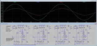
Ith this simulatiuon output,
- red is the original circuit (this forum member Hans Polak's simulation)
- Green is the new design with the MC input
As you see, there is a slight difference that I hesistate to call an improvement (the small lift might give a slight impression of warmth).

As the jFET I have failed to use the 2SK170 (can't get the model to load) So I used another one but the working principle could be established. And that is my goal.
So, to present the conclusions:
- The MC stage in the cathode lead can be connected without a capacitor and the ECC83 will 'float'.
- No effect on the Vak and Vbk, same working points
- NO effect on the internal resistance of the first stage ECC83 - most important issue as this is where the very short feedback circuit connects.
- Curve shows a reduced bump in the low bass (around 20 Hz), where the original cicuit has 0.2 dB lift.
- Due to the cathode coupling of the input, the high get frequencies have more breath in them. No MILLER capacitance in the first tube!
- The circuit is very sensitive to the precise power supply
- It still has the 6 dB extra correction of the EAR compared to the theoretical value;
- It is very easy to reduce the FET input amplification by 6 dB by reducing the Rdrain.
Ith this simulatiuon output,
- red is the original circuit (this forum member Hans Polak's simulation)
- Green is the new design with the MC input
As you see, there is a slight difference that I hesistate to call an improvement (the small lift might give a slight impression of warmth).
The circuit
Why chose a circuit with feedback?
The original TdP EAR834 circuit has and RIAA that has been tweaked a bit by the LencoHeaven guys (if i am correct, by amongst others, Loersch) to obtain a flatter response. I have take these "modern" revised components (the difference in the high frequencies is large, it is now >0.2 dB flatter).
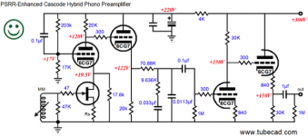
As you see I have an extra power supply for the FET drain current: that is needed because the firtst ECC83 only conducts some 0,7 mA and that is not enough for the input FET. I need to get some extra juice somewhere else. I am considering other circuits too. But for now this suffices.

In the simulation, I have use a stock FET from LTSpice, I have yet to load the LSK386 I will use to the library (my attempts failed; I have a Mac and things work different here) but the principle of connecting the two "stages" as cascode is clear: Connect the cathode to the drain and have a separate drain resistor.
Why chose a circuit with feedback?
FB over two stages (two tubes) feedback gives large time lag and phase errors.
But the brilliance of TdP's circuit is that the circuit is: FB just across ONE tube.
This is well behaved. The only comment I have is that the feedback margin of an RIAA curve with feedback differs with frequency. This implies the content of harmonics change slightly with frequency. [But I have never heard anyone complain about that, nor state that this is the big benefit of a passive design . . . ]
The original TdP EAR834 circuit has and RIAA that has been tweaked a bit by the LencoHeaven guys (if i am correct, by amongst others, Loersch) to obtain a flatter response. I have take these "modern" revised components (the difference in the high frequencies is large, it is now >0.2 dB flatter).
As you see I have an extra power supply for the FET drain current: that is needed because the firtst ECC83 only conducts some 0,7 mA and that is not enough for the input FET. I need to get some extra juice somewhere else. I am considering other circuits too. But for now this suffices.
In the simulation, I have use a stock FET from LTSpice, I have yet to load the LSK386 I will use to the library (my attempts failed; I have a Mac and things work different here) but the principle of connecting the two "stages" as cascode is clear: Connect the cathode to the drain and have a separate drain resistor.
As a side note, Simulation guru John Broskie warns against the cascoding of FET input and the first tube, because the PSRR is virtually zero. He proposes a Loftin-White coupling. But that has a reduced amplification by some 25 dB. The only way to use it is having a LW coupling with a very large Rk and hence it starts to look like a gyrator. That is not of my liking. It means introducing a capacitor. In my circuit as I have used it since the eighties it is not needed.
About the L-W:
John Broskie proposes a Loftin-White coupling. "We can make a cascode with the FET receiving the input signal or we can cascade the FET into the tube in a Loftin-White like configuration, which may result in lower noise and a more tube-like sound."[/INDENT]
I like his mention of 'tube-like sound' I have yet to do a proper simulation of the latter; I for now have stuck to my first circuit from the eighties with a cascode.
... As you see I have an extra power supply for the FET drain current: that is needed because the firtst ECC83 only conducts some 0,7 mA and that is not enough for the input FET....
As a side note,Simulation guru John Broskie warns against the cascoding of FET input and the first tube, because the PSRR is virtually zero...
One alternative is to use a beefier triode like the ECC82 (12AU7) or the ECC88 (6DJ8) instead of the '83 and run the FET straight into the cathode, as usual. It makes a much simpler circuit and the theoretical performance should be similar, being largely determined by the FET.
I think the importance of the poor PSRR of the cascode is overrated: a single ECC83 yields no more than about 3-9 dB of PSRR, depending on the operating conditions. A cascode yields 0 dB straight, or about 3 dB if you apply Broskie's compensation scheme by tying the bypass capacitor to Vb instead of ground. So basically, we're talking about a few dB's difference, and that can be fixed with better filtering of the Vb.
Good suggestions.
However, the feedback is against the Ra' (about 390k)//Ra (330k)and // the load (Rg 2Meg), so I must adhere to this.
I have thought out alternatives here (such as a CCS into a ECC82 and that would allow me to dial in the correct Rtotal immediately.) I'll keep that for an experiment.
Myself I also had my first cascode very clean; probably I messed up my earth and or messed up the filament supply.
Thanks for the figures about the effect of the broskie compensation, 3dB is not a major design goal specifically if it adds a feedback pole.
I have a 277 V Salas Shunt behaving very good. So that can subsequently only be spoilt with bad, multiple and confusing earth lines - and that is why I bought the PCB boards.
However, the feedback is against the Ra' (about 390k)//Ra (330k)and // the load (Rg 2Meg), so I must adhere to this.
I have thought out alternatives here (such as a CCS into a ECC82 and that would allow me to dial in the correct Rtotal immediately.) I'll keep that for an experiment.
Myself I also had my first cascode very clean; probably I messed up my earth and or messed up the filament supply.
Filament is important - mind you, when I tried a DC-DC converter to 6.3 volts I could see the 70 kHz oscilator sine/rectification pump effect (less than 10 mV) on the output of a preamp (some 2-3 mV) so that coupling it is very sensitive.
Thanks for the figures about the effect of the broskie compensation, 3dB is not a major design goal specifically if it adds a feedback pole.
I have a 277 V Salas Shunt behaving very good. So that can subsequently only be spoilt with bad, multiple and confusing earth lines - and that is why I bought the PCB boards.
... However, the feedback is against the Ra' (about 390k)//Ra (330k)and // the load (Rg 2Meg)...
Thanks for the figures about the effect of the broskie compensation, 3dB is not a major design goal specifically if it adds a feedback pole.
I have a 277 V Salas Shunt behaving very good. So that can subsequently only be spoilt with bad, multiple and confusing earth lines - and that is why I bought the PCB boards.
True, I'm confronted with the same issue, and I simply scale down the RIAA EQ to the lower Ra, with lower noise thrown in as a free bonus.
Here's the sim of the various PSRR schemes under consideration; I simply inject 1V at 100Hz to the power line.
- V(out1) is unbypassed upper grid
- V(out2) is bypassed upper grid, the "normal" scheme
- V(out3) & V(out4) are with the Broskie trick and different values
Attachments
You'll have to anyway: the original EQ is designed for a source of 100K or less, but cascoding it will make it a lot more 🙂.
Don't worry, it's just simple arithmetics to get you started, then use LTspice to fine tune.
Don't worry, it's just simple arithmetics to get you started, then use LTspice to fine tune.
Progress report

This is with actual measured components (using computerized L/C meter)
Not bad isn't it?
This is with actual measured components (using computerized L/C meter)
Not bad isn't it?
I measured the parasitic capacitance of the [black Zhilly] boards, and it is 0,3 pf for the 100pF position, and 0,2 pF for the 300 pf position. When that is added to the simulation, the nice curve I had is influenced in a negligent way. The HF roll-off stays at -3dB/51 kHz. Great.
I tried to make a cut in the board to reduce the parasitic capacitance, but it is made of black thermo-elastic plastic so it melts under my dremel.
I tried to make a cut in the board to reduce the parasitic capacitance, but it is made of black thermo-elastic plastic so it melts under my dremel.
Last edited:
View attachment 724096
This is with actual measured components (using computerized L/C meter)
Not bad isn't it?

For those who want to know what I am doing:
it is a merger of
- the simple LePacific design by William Walther of Maison de l'Audiophile in Paris, a Moving Coil prepre amplifier that can be found on diyaudioprojects. Boozhound added a gate resistor which is smart as it reduces the noise of the FET. You can get a PCB there.
- the 'simple' EAR834 by Tim de Paravicini (It's not simple at all, the components come very close and have big impact.) It has feedback but only over one tube stage which means that phase differences are small. It is venerated. Look for it at the bay.
--> and no coupling cap
Last edited:
I now also have positive feedback on tube V2.
I simulates quite well. The summing node is at -60dB and straight up to 10 kHz (dependent on level) while the decoupled cathode resistor has a higher low freq residue of less than 30dB reduction . . .
However, I found that Norman Koren discussed PFb in the PAS phono amplifier:
Never the less I have found a way to compare the two schemas with and without PFb and still significantly improve the effect of superior low freq decoupling along the way in the latter.
I simulates quite well. The summing node is at -60dB and straight up to 10 kHz (dependent on level) while the decoupled cathode resistor has a higher low freq residue of less than 30dB reduction . . .
However, I found that Norman Koren discussed PFb in the PAS phono amplifier:
Positive feedback is generally undesirable because it exacerbates the differences between tubes, i.e., open loop gain can vary by more than the tubes themselves. Without RPFB, the open loop gain drops by 4.4dB to 62.3dB. Since the preamp gain is 61dB around 25Hz, negative feedback is nearly absent at low frequencies. This means that the low frequency response is very sensitive to tube variations and can be different for different versions of the 12AX7 (suffixes A, B, WB, etc.). Mercifully, the response will become flatter- for a while- as tubes age and increased plate resistance reduces circuit gain. [Note his commemts relate to his own amp]
Never the less I have found a way to compare the two schemas with and without PFb and still significantly improve the effect of superior low freq decoupling along the way in the latter.
- Status
- Not open for further replies.
- Home
- Source & Line
- Analogue Source
- Direct MC input stage for EAR834