Hi all...
I have verified that the reset is being done, and that valid SPDIF data is going into the DIR1703 (after a 74HC04).
CKSEL and UNLOCK are connected.
For some reason though, UNLOCK is always staying high, and DOUT is always staying low (the output clocks are working though at the crystal rate).
I cant work it out. Any sugestions?
Thanks.
I have same problems with 16.934 clock feeding it from cd player spdif.
May be problem with pll filter components?
good luck,
borisov57
May be problem with pll filter components?
good luck,
borisov57
DIR1703
Try to get the sp/dif data from cd rom's digital out (as it plays an audio cd).
Dout (pin12) will be muted (low) in all conditions unless the PLL will lock to the signal.
Check that the crystal is oscillating. Use a Colpits oscillator.
Check the filter components (R2, C7 and C8). Connect them to GND.
Change DIR1703.
good luck
What have you done with the CKSEL pin? Connected it to UNLOCK?
When CKSEL is high crystal mode is selected. In this mode the output clocks are generated from the crystal oscillator and Dout is held low. This most likely the mode your setup is running in.
UNLOCK staying high means the PLL is not locking to the input signal for whatever reason. How is your soldering of the SSOP package?
Hi MWP,
Maybe souncards outputs 48 kHz sample rate and you need 256 x 48 kHz crystal;
12.288 Mhz.
Good luck,
Aleksander
Maybe souncards outputs 48 kHz sample rate and you need 256 x 48 kHz crystal;
12.288 Mhz.
Good luck,
Aleksander
Please post your reciever circuit (comparator/everything before the DIR). Sounds like a likely place for an error.
Have you verified this with a scope? How do you know?I have verified that the reset is being done, and that valid SPDIF data is going into the DIR1703 (after a 74HC04).
If you are interested I will post another such cobbled-together circuit after work which I have verified works. The correct way to do this of course is a comparator.
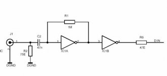
This is circuit which i use for input.
The 74HC04 must be an unbuffered part such as a 74HCU04 for the 1 Meg bias resistor to work. Change R1 from 1Meg to 50K and put a 2K (or 2.2K 5%) resistor in series with the input cap C2 and the input connection to pin 1 and R1 and you will have a very good input circuit that has a gain of about 25 and will sound better than most comparators. For driving the Crystal input receivers (8412 8414 ect) use this circuit to drive a 74HC86 connected as a phase inverter to drive both inputs differentially. This makes an excellent front end circuit and is much better than driving the Crystal receiver directly. I have used this front end and it sounds great. The 47 ohm resistor could be about 25 to 30 ohms for better source termination, but I would not remove it.
http://www.fet.uni-hannover.de/~purnhage/dat/spdif.txt
http://www-us9.semiconductors.com/cgi-bin/pldb/pip/74HCU04/
http://www.epanorama.net/documents/audio/spdif.html
Thanks for the input guys.
I have been away for the last week, hence my lack of replies to your sugestions.
Before i went away, my 80Gb HDD also died meaning i have no access to my Protel DXP schematics at the moment (i didnt loose them, i just cant install DXP to view them until i get a new HDD).
But i do have another question that the PDF doesnt answer.
What happens if CKSEL is set to generate the clock using the PLL inseatd of the crystal, and there is no input present?
If i do this, can i leave out the crystal?
As itll be 99% of the time connected to a PC soundcard which will always generate a SPDIF signal while turned on, i have no problem reseting the DAC manually when i use the PC.
DIR1703 Clock Source
The DIR1703 operates off of two clocks:
One (PLL1) regulates the SpAct mechanism. This requires that a crystal (or another external oscillator source) always be connected to XTI(/XTO).
The other (PLL2) is the main system clock for the audio data.
If the CKSEL pin is set low, then PLL2 is generated from the incoming S/PDIF data stream. If the S/PDIF then disappears, then PLL2 will just continue to run at the last tracked frequency.
If the CKSEL pin is set high, then PLL2 is sourced from PLL1. If this option is used (most people won't), then the S/PDIF transmitter must have its clock synched to PLL1.
In their application notes, TI shows a nice trick to get the DIR1703 running before any S/PDIF is received:
By tying the UNLOCK output to the CKSEL input, then PLL2 is sourced from PLL1 when there is no S/PDIF present. When S/PDIF appears, then PLL2 will be switched to track the S/PDIF stream.
The short answer to your question is that you always need an external crystal or other external clock source.
Regards,
Brian.
MWP said:
But i do have another question that the PDF doesnt answer.
What happens if CKSEL is set to generate the clock using the PLL inseatd of the crystal, and there is no input present?
If i do this, can i leave out the crystal?
The DIR1703 operates off of two clocks:
One (PLL1) regulates the SpAct mechanism. This requires that a crystal (or another external oscillator source) always be connected to XTI(/XTO).
The other (PLL2) is the main system clock for the audio data.
If the CKSEL pin is set low, then PLL2 is generated from the incoming S/PDIF data stream. If the S/PDIF then disappears, then PLL2 will just continue to run at the last tracked frequency.
If the CKSEL pin is set high, then PLL2 is sourced from PLL1. If this option is used (most people won't), then the S/PDIF transmitter must have its clock synched to PLL1.
In their application notes, TI shows a nice trick to get the DIR1703 running before any S/PDIF is received:
By tying the UNLOCK output to the CKSEL input, then PLL2 is sourced from PLL1 when there is no S/PDIF present. When S/PDIF appears, then PLL2 will be switched to track the S/PDIF stream.
The short answer to your question is that you always need an external crystal or other external clock source.
Regards,
Brian.
Well you can use the LOCK signal as a mute or reset signal for the DAC.
I have a hunch the reciever was a big problem with your earlier circuit.
I have a hunch the reciever was a big problem with your earlier circuit.
Re: This is circuit which i use for input.
Do you feel this circuit is better than this one:
http://www.diyaudio.com/forums/show...age=15&highlight=transformerless&pagenumber=7
? (last version I posted)😉
Hi Fred,Fred Dieckmann said:The 74HC04 must be an unbuffered part such as a 74HCU04 for the 1 Meg bias resistor to work. Change R1 from 1Meg to 50K and put a 2K (or 2.2K 5%) resistor in series with the input cap C2 and the input connection to pin 1 and R1 and you will have a very good input circuit that has a gain of about 25 and will sound better than most comparators. For driving the Crystal input receivers (8412 8414 ect) use this circuit to drive a 74HC86 connected as a phase inverter to drive both inputs differentially. This makes an excellent front end circuit and is much better than driving the Crystal receiver directly. I have used this front end and it sounds great. The 47 ohm resistor could be about 25 to 30 ohms for better source termination, but I would not remove it.
Do you feel this circuit is better than this one:
http://www.diyaudio.com/forums/show...age=15&highlight=transformerless&pagenumber=7
? (last version I posted)😉
Ugh... i dont know how i could have got so many things wrong in my design. Must have happened during routing the PCB.
I had BRSEL grounded (instead of unconnected), CKTRANS connected with SCKO and a few other things wrong.
New problem:
I have a D3.3V (DGND) supply and a A3.3V (AGND) supply for the DIR1703 PCB. Each is has its own tranformer rectified by LM337s set at 3.35V, with the two grounds only meeting on the power supply PCB.
But its frying DIR1703s. After waiting a while, i see very small sparks and smoke from the ICs leads around the A3.3V supply. But ive now tripple checked all connections, and they are fine. Ive made sure that the supplies are 3.35V using a DMM.
Is there any chance that my 3.3V lines are somehow oscilating and creating false readings on my DMM?
Im going to try and borrow a crappy CRO later this week.
Power Supply Restrictions
Using separate supplies for this part could be very tricky.
Note that in the data sheet:
absolute maximum ratings
Supply voltage differences, Vcc, Vdd........ +/-0.1V
This means that the supplies have to match within 0.1V not only during operation, but also that they have to precisely track each other during power up and down.
0.1V is too small to allow the use of power supply safety diodes tying the two together (0.3V is usually the limit).
The only way to use separate supplies would be to come up with a design that forced them to track each other during power cycling. This could be done, but it's probably more practical to use a single supply and isolate the power pins. TI shows some examples in their application notes.
Regards,
Brian.
MWP said:
New problem:
I have a D3.3V (DGND) supply and a A3.3V (AGND) supply for the DIR1703 PCB. Each is has its own tranformer rectified by LM337s set at 3.35V, with the two grounds only meeting on the power supply PCB.
But its frying DIR1703s. After waiting a while, i see very small sparks and smoke from the ICs leads around the A3.3V supply.
Using separate supplies for this part could be very tricky.
Note that in the data sheet:
absolute maximum ratings
Supply voltage differences, Vcc, Vdd........ +/-0.1V
This means that the supplies have to match within 0.1V not only during operation, but also that they have to precisely track each other during power up and down.
0.1V is too small to allow the use of power supply safety diodes tying the two together (0.3V is usually the limit).
The only way to use separate supplies would be to come up with a design that forced them to track each other during power cycling. This could be done, but it's probably more practical to use a single supply and isolate the power pins. TI shows some examples in their application notes.
Regards,
Brian.
- Status
- Not open for further replies.
- Home
- Source & Line
- Digital Source
- DIR1703 Problems