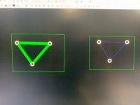
What is the correct way to connect a component pad to a ground plane?
Would you make a ground plane, make a trace between all the components that go to ground and tell the ground plane to connect to that net or use the thermal settings for each pad and tell it to connect directly to the pad. When I try that, I get a lot of errors when I run verification. When I connect all the pads with a trace and connect that net to the GP no errors.
Would you make a ground plane, make a trace between all the components that go to ground and tell the ground plane to connect to that net or use the thermal settings for each pad and tell it to connect directly to the pad. When I try that, I get a lot of errors when I run verification. When I connect all the pads with a trace and connect that net to the GP no errors.
Not an expert , but...
Both ways are good.
Having Some pads( same side ) connected using manual routing will create automatically a net. Then if you want a ground plane connected to those pads you will use the “place copper pour” , create your shape and right click on edge of the plane shape , properties , connectivity and connect to the net you just created.
Exactly the Same way using the ratline, connect the pads will create a net, place copper pour, connect the copper pour to the net.
You should have no errors , just make sure to connect the copper pours to the right net.
Last edited:
I use a copper pour and just run tracks the to pads.
You don't want the pad to merge into the pour or it will be hard to solder due to the heatsinking effect.
Each copper pour should be able to connect to a netname so that you can connect the pour to say GND or whatever.
If the netname of the track matches the netname of the copper pour the tracks should blend into the copper pour but not the pads.
There is an option to use a two or four prong spoke to attach the pad to the copper pour. It helps to minimize the "heatsink" effect that you mention. Thanks you guys.
Nigel,
Your S/W does not create thermal ties in copper pours?
In Orcad you can create a pour which makes ties/spokes or a cooper area which is full contact. Ties can be defined by widths, for small and large plt holes.
Your S/W does not create thermal ties in copper pours?
In Orcad you can create a pour which makes ties/spokes or a cooper area which is full contact. Ties can be defined by widths, for small and large plt holes.
Nigel,
Your S/W does not create thermal ties in copper pours?
In Orcad you can create a pour which makes ties/spokes or a cooper area which is full contact. Ties can be defined by widths, for small and large plt holes.
I haven't found a need for thermal spokes.
There will be a track going to the pad anyway so that will connect to copper pour too.
An externally hosted image should be here but it was not working when we last tested it.
Sorry OP, this is off topic, but could be of interest to others.
Also in Orcad ( and other s/w I have used), you do not need to make a track (connection) to the pad that gets surrounded by a Cu pour, if it is part of the same net, it will get the thermal as it connection to the net. This can save you lots of time if there are many of them, like grounds, supplies etc.
Okay then, how do you deal with a negative planes with the requirement to have thermals connections to the plane?I haven't found a need for thermal spokes.
Also in Orcad ( and other s/w I have used), you do not need to make a track (connection) to the pad that gets surrounded by a Cu pour, if it is part of the same net, it will get the thermal as it connection to the net. This can save you lots of time if there are many of them, like grounds, supplies etc.
- Status
- Not open for further replies.
- Home
- Design & Build
- Software Tools
- Diptrace question
