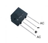
There are lots of bridge rectifiers that look like that (RS606) accept I have never seen one that has the AC inputs on the outside of the package , everyone i have seen has the AC inputs on the two inside pins and the DC on the outside pins , I suppose if you need one with the AC on the outside pins you can insulate the pins with heatshrink and then bend them into the position you need ......
cheers
The Picture in your post has the AC on the inside pins but you labeled them differently .....
cheers
The Picture in your post has the AC on the inside pins but you labeled them differently .....
It is the writting that is erratic. It is the same u have seen with ac terminlas inside.
Gajanan Phadte
Gajanan Phadte
Marks what I have written is what I need, so I need the model with AC terminals not at the middle pins, AC terminals should be at the first and fourth pin.
Or rotate the thing 90 degrees and bend the legs foreward and backward to fit the holes.
It is just a rectifier, doesn;t matter what it looks like.
It is just a rectifier, doesn;t matter what it looks like.
Hi,
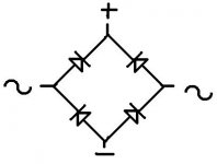
In and out pins don't make any difference, for a bridge they are reversible.
rgds, sreten.
Wrong, draw it out.
The only terminals that can be switched are the two AC inputs...those two can be switched with each other...all others NOT
Attachments
Like me and Enzo suggested , if you need AC on the outside pins just insuleate the pins with heatshrink and bend them into the desired position , Rectifiers like the RS606 have long and very thick pins so it is easy to bend the pins into any position and not worry about them breaking because of vibration fatigue .....
I also second "KatieandDad" suggestion in just making a bridge out of diodes .... When i build my Guitar tube preamp I needed a high voltage inline bridge rectifier but didn"t have one so I used 4 Diodes soldered it together P2P and used that as my diode bridge and it works well ......
Cheers
I also second "KatieandDad" suggestion in just making a bridge out of diodes .... When i build my Guitar tube preamp I needed a high voltage inline bridge rectifier but didn"t have one so I used 4 Diodes soldered it together P2P and used that as my diode bridge and it works well ......
Cheers
Looks like a standard case from the image with the AC on the inner two pins and + marked with the cut corner.
I have several. This is the only variation I know and the cut corner denotes the +pin. The package is used for various voltages and currents check your local supplier. CPC for example have several like this Rectifier
here are some more Surplectronics
I have several. This is the only variation I know and the cut corner denotes the +pin. The package is used for various voltages and currents check your local supplier. CPC for example have several like this Rectifier
here are some more Surplectronics
Last edited:
- Status
- Not open for further replies.
- Home
- Design & Build
- Parts
- Diode bridge rectifier