Hi everyone,
I've recently assembled a breadboard DAC prototype based on the AD1862s with an AD811 I/V stage, when I test this board with my headphone amplifier board it seems to work fine.
I've also tried to add preamp and equalizer stages from Yamaha and Behringer in the middle (between the DAC and HP amp board) and everything is also ok, no sound issues, even if I move the sliders or knobs all way up or down.
Now I'm trying to put a preamp breadboard between the DAC prototype and HP amp (to perform some small L/R balance, volume and tone controls). I've noticed that whenever I play some sound or music in the DAC board I get an hiss, white noise like, on the left channel which is really anoying, even when I turn the preamp input pot all the way down, the noise is still there and it is only present when audio is being played, I don't know what is going on, since the right channel seems fine. It gets worse if I add some treble gain. Any ideas of what should I look for?
All the Best,
Danny
Post the preamp schematic.
Have you tried a different source than the DAC, to see if there is still noise?
Have you tried a different source than the DAC, to see if there is still noise?
Last edited:
The noise is there even without the DAC connected, if there is some digital signal on the setup, when the I2S board is connected and some sound is being played there is noise, the DAC board can be completely off.
EDIT:
I haven't tried yet but it should work fine if no digital circuits are present in the setup.
EDIT:
I haven't tried yet but it should work fine if no digital circuits are present in the setup.
Try turning off all digital circuits, computers, LED lights, etc. in the house to see if the noise is still present.
Also try inserting shorting plugs into the preamp inputs.
Also try inserting shorting plugs into the preamp inputs.
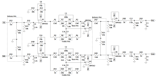
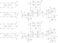
Here are the schematics of the preamp and DAC boards.
EDIT:
I have tried to switch the computer on and off and the LED lights also, it makes no difference, only the digital circuit of the setup seems to cause the noise.
When the balance pot. is adjusted to full left or full right, there is a lot of noise on the cutoff channel, if digital circuits are on. The higher the treble pot. setting the higher the noise.
The noise seems to not be present after the first stage (voltage gain).
Attachments
Last edited:
So you are certain that the DAC causes the noise? Turning it off kills the noise?
Is the DAC in the same chassis as the tone circuit? How about some photos?
Is the DAC in the same chassis as the tone circuit? How about some photos?
No it is not the DAC that causes the noise it's the digital circuits, the optical to I2S board (DIR9001), the inverter and the two shift registers.So you are certain that the DAC causes the noise? Turning it off kills the noise?
So no, turning it off does not kill the noise, maybe it lowers a bit but I'm not 100% sure.
I don't have a chassis yet 🤣Is the DAC in the same chassis as the tone circuit? How about some photos?
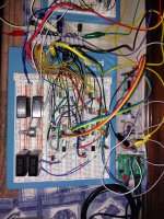
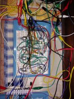
This is a breadboard prototype, which uses 3 breadboards and 2 PCBs, I can send you a picture tomorrow, but it looks very messy. 😛
It is powered by 4x9V NiMH 320mAh batteries and a 5V Li-Ion 10000 mAh battery.
The chassis is just whatever the pcb is mounted on. Prototypes are always messy.
Can you post schematics and photos of the optical to I2S board, the inverter, and the two shift registers?
Are the batteries charged only when not being used? Is the digital ground independent of the analog ground?
If noise is only in one channel, that is a good sign.
Can you post schematics and photos of the optical to I2S board, the inverter, and the two shift registers?
Are the batteries charged only when not being used? Is the digital ground independent of the analog ground?
If noise is only in one channel, that is a good sign.
Last edited:
In addition :
Are the the supply pins of the two 4562 properly decoupled ? With 100nF to GND ?
4562 is fast and easily enter in oscillation, you could try adding a 100 Ohms in the negative feedback path of the two output buffers : between 4562 output and neg input.
Not difficult to test on a breadboard.
Are the the supply pins of the two 4562 properly decoupled ? With 100nF to GND ?
4562 is fast and easily enter in oscillation, you could try adding a 100 Ohms in the negative feedback path of the two output buffers : between 4562 output and neg input.
Not difficult to test on a breadboard.
I have no experience with AD1862 but it seems that pin 1 and 2 should not be connected together to negative analog supply.
Negative analog supply should go be connected to pin2 and a dedicated cap should be connected to pin1.
see AD datasheet :

see also DIYAudio member miro1360 implementation :

( https://www.diyaudio.com/community/threads/dac-ad1862-almost-tht-i2s-input-nos-r-2r.354078/ )
Not sure it has influence on your noise issue, but that should be checked.
Negative analog supply should go be connected to pin2 and a dedicated cap should be connected to pin1.
see AD datasheet :
see also DIYAudio member miro1360 implementation :
( https://www.diyaudio.com/community/threads/dac-ad1862-almost-tht-i2s-input-nos-r-2r.354078/ )
Not sure it has influence on your noise issue, but that should be checked.

Thank you very much for helping me AIM65.
It doesn't seem like oscillation, because if I stop playing audio in my PC the noise stops.
I have a 100 nF capacitor in parallel with a 10 uF capacitor connected between +Vs and -Vs, but not to GND.Are the the supply pins of the two 4562 properly decoupled ? With 100nF to GND ?
4562 is fast and easily enter in oscillation, you could try adding a 100 Ohms in the negative feedback path of the two output buffers : between 4562 output and neg input.
Not difficult to test on a breadboard.
It doesn't seem like oscillation, because if I stop playing audio in my PC the noise stops.
Thank you for pointing out this issue, I've changed that in the breadboard, I forgot to change on the diagram, I'm sorry.I have no experience with AD1862 but it seems that pin 1 and 2 should not be connected together to negative analog supply.
Negative analog supply should go be connected to pin2 and a dedicated cap should be connected to pin1.
I definitely agree, but I like to test everything on more flexible prototypes before proceeding with a PCB design. I'm also very bad at soldering things, my hands shake a lot, most of the times I end up damaging the circuits and burning myself, I only have a few successful PCBs. Soldering SMDs such as the shift registers in Miro's DAC board is nearly impossible to me. 😢Also, these circuits will not work very well on a breadboard. They need a ground plane.
I would suggest, instead of soldered circuits on a perfboard, that you try a solderless breadboard.
With careful planning, even without the ground plane, you can get compact circuits that will work
pretty well before moving to a pcb with ground plane. Use the pre-stripped and formed wires that
are made for it. I have had very good results using these with thoughtful planning. They are completely reusable.
Small pcb adapters for SMT to TH are also available. There are many kinds of breadboards, an example:
https://digilent.com/shop/solderless-breadboard-kit-large/
https://digilent.com/shop/breadboard-wire-kit/
It could still be oscillation induced by the signal.I have a 100 nF capacitor in parallel with a 10 uF capacitor connected between +Vs and -Vs, but not to GND.
It doesn't seem like oscillation, because if I stop playing audio in my PC the noise stops.
I can't hear the noise, if I reinforce the GND with like 3 aligator clips per breadboard, however, the noise is always there if I move the balance pot to the extreme positions, what can be happening?
Some photos of the terrible mess 😋
Some photos of the terrible mess 😋
Attachments

Then you are using solderless breadboards. An advantage of these is that the layout can be
rather similar to a pcb layout if carefully planned, preferably done with the short, precut solid wires.
Since one channel does work correctly, and troubleshooting this would be problematic, you can
probably, with some justification, assume the noise will be gone when the actual pcb layout is done.
You could certainly lower the balance pot impedance, and just use a single 10k pot.
With the power off, you can check ground continuity from each circuit ground to the power supply ground.
Especially make sure the balance control wiper reads zero ohms to ground at all times.
Some types of solderless breadboards have breaks in the power supply bus lines (at the sides),
that may not be expected.
Last edited:
It's a good thing that these AD811s work at all in those conditions and they are still without a heatsinks.I can't hear the noise, if I reinforce the GND with like 3 aligator clips per breadboard, however, the noise is always there if I move the balance pot to the extreme positions, what can be happening?
Some photos of the terrible mess 😋
Surely AD811 is a source of noise, i.e. self-oscillation.
- Home
- Source & Line
- Digital Line Level
- Digital noise/interference on the left channel