Hi,
my name is Alfred Rosenkraenzer, I worked 36 years as a design engineer, mainly on analog and digital signal designs.
Now I am on early retirement.
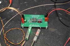
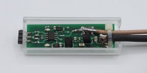
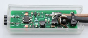
I designed two differential current probes to measure the current in a shunt resistor with a scope. These are pretty helpful if you like to measure eg the current in the emitter resistors of an audio power amplifier, or at switching power supplies.
There are two articles about them in ELEKTOR:
https://www.elektormagazine.com/magazine/elektor-201609/39807
https://www.elektormagazine.com/magazine/elektor-159/59112
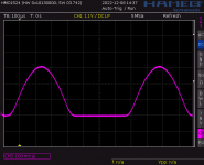
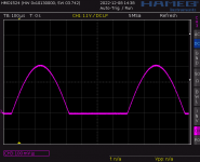
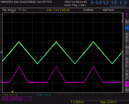
Attached are some screen shots from the emitter resistor of an amp.
On SCR01 the yellow trace is the output of the amp at 8 Ohm, purple the upper emitter current.
Note the difference in bias current between SCR02 and SCR03. Look at the end and the start of the half sine.
If someone is interested I can send you more info.
I still have some blank boards which I can sell.
Best regards
Alfred
my name is Alfred Rosenkraenzer, I worked 36 years as a design engineer, mainly on analog and digital signal designs.
Now I am on early retirement.
I designed two differential current probes to measure the current in a shunt resistor with a scope. These are pretty helpful if you like to measure eg the current in the emitter resistors of an audio power amplifier, or at switching power supplies.
There are two articles about them in ELEKTOR:
https://www.elektormagazine.com/magazine/elektor-201609/39807
https://www.elektormagazine.com/magazine/elektor-159/59112
Attached are some screen shots from the emitter resistor of an amp.
On SCR01 the yellow trace is the output of the amp at 8 Ohm, purple the upper emitter current.
Note the difference in bias current between SCR02 and SCR03. Look at the end and the start of the half sine.
If someone is interested I can send you more info.
I still have some blank boards which I can sell.
Best regards
Alfred
Attachments

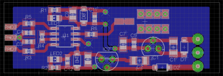
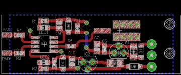
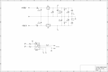
Here come some more pictures, schematics and layout
Attachments

Very nice!
I don't have an immediate need but it is really a good solution for measuring current in the presence of common mode signal.
Jan
I don't have an immediate need but it is really a good solution for measuring current in the presence of common mode signal.
Jan
Hi all,
some more infos:
There two versions.
Version 1 uses the AD8479. It has a fixed gain of one and a bandwidth of about 130 kHz. The common mode range is very big, with a power supply of +-12V about +-500 V. To be honest I never used more than +-80 V. This is very useful to measure at audio power amps. To measure at switching power supplies, the bandwidth is sometimes to small.
Version 2 uses the AD8421. The gain is adjustable with a resistor up to 100. The bandwidth is much wider, but depends on the gain. But the common mode is limited to the power supply rails. Using +-12 V the common mode range is about +-10 V, so 2 V inside the rails. But it is possible to use asymmetrical power like +18 and -5V. This is very good to measure at switching power supplies.
There is a newer part from TI INA849 which is pin compatible and gives you even more bandwidth.
I have two kinds of PCB board for this. The one I did uses the chip in a SOIC8 package (still possible to solder) and the regulators in the through hole package (better availability)
ELEKTOR redesigned it to the smaller MSOP package and SMD regulators.
Each PCB is 5 Euro plus shipping. I also have the small housing and coax cables.
But I have no chips anymore.
I added the datasheets.
Have a look at my home page.
www.alfredrosenkraenzer.de (sorry, in german)
There you will find my EMail address.
Alfred
Attachments
- Home
- Design & Build
- Equipment & Tools
- Differential Current Probes