Hi all,
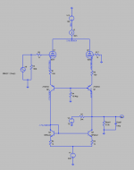
I'm playing around with various driver topologies, and I've come up with the following. It uses current mirrors to develop a voltage across a large value resistor RL.
The one thing I can't figure out is how to arrange this so that the output swings around 0V, rather than around ~150V as it does at the moment. I'd be very grateful for any suggestions.
Kind regards, Ed.
Attachments

Hi Ed,
the actual plate dissipation of 2.5 W per triode well exceeds the ECC88 1.8 W rating!
What about arranging the triode pair as a real differential amplifier instead of just a prima vista one?
Best regards!
the actual plate dissipation of 2.5 W per triode well exceeds the ECC88 1.8 W rating!
What about arranging the triode pair as a real differential amplifier instead of just a prima vista one?
Best regards!
Ah yes, that's a good point about the bias conditions.
Regarding the topology, I don't think a conventional tube-based differential amplifier would give the voltage swing required.
Regarding the topology, I don't think a conventional tube-based differential amplifier would give the voltage swing required.
If you use a current mirror there has to be a current to mirror. Here you feed it a voltage 🙁
Mona
Mona

If you want it to swing around 0V, use a bipolar supply.
Try a 6SN7 instead of 6DJ8 as it will handle the power.
Try a 6SN7 instead of 6DJ8 as it will handle the power.
Still don't get what the current source in the common plate supply (Long Head Pair??) and the right triode really do...
Also note the whopping 4 W plate dissipation with each triode.
Best regards!
Also note the whopping 4 W plate dissipation with each triode.
Best regards!
Last edited:
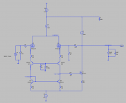
My thinking is that, using this arrangement, I could then use a source follower on the output and wrap feedback around the whole thing.
(Incidentally I think the previous diagram didn't have the correct voltages on it - perhaps I didn't re-run the simulation correctly and some figures were left over from a previous run. Anode dissipation is about ~2W.)
(Incidentally I think the previous diagram didn't have the correct voltages on it - perhaps I didn't re-run the simulation correctly and some figures were left over from a previous run. Anode dissipation is about ~2W.)
Attachments
- Home
- Amplifiers
- Tubes / Valves
- Differential current mirror driver