I've built a clone of an old Gibson GA-5W transistor guitar amp (schematic attached), because I liked the sound of one that I heard and wanted to understand it better. Simple thing with a common emitter BJT preamp stage, and a push-pull power stage that I don't 100% understand yet.
It passes signal, but the sound is fuzzy and distorted, at all volume levels. I've checked a bunch of connections and component values, and tested it against the voltages given on the schematic, and everything looks about right. I've also poked around with my scope and a signal generator: if I isolate the first stage, its output looks great, no problems there. At the speaker connection, the signal is asymmetrically distorted, and looks pretty similar regardless of signal volume. It doesn't look like crossover distortion to me, and doesn't respond much to changing the bias trimpot.
So, something going wrong after Q1. I tried looking at the signal at a few other points, but I don't really understand what I'm seeing:
- When I connect the first stage to Q2, the signal on the base of Q2 looks very distorted — I guess I'd describe it as extremely clipped on the bottom of the waveform. It looks significantly worse than the output signal at the speaker!
- At the collector of Q2 / base of Q3, I can barely see the signal because there's a pretty loud sawtooth at about 2khz.
- At the base of Q4, I see something that looks similar to the base of Q2, but with a lot of high frequency noise right where the wave is most distorted.
I'm a little bit stumped. My usual approach would be to isolate sections of the circuit, but Q2-5 all kind of work together. I also don't really understand how Q2 and Q3 are working here. I'd appreciate any advice or suggestions.

View attachment GA5W.PDF
It passes signal, but the sound is fuzzy and distorted, at all volume levels. I've checked a bunch of connections and component values, and tested it against the voltages given on the schematic, and everything looks about right. I've also poked around with my scope and a signal generator: if I isolate the first stage, its output looks great, no problems there. At the speaker connection, the signal is asymmetrically distorted, and looks pretty similar regardless of signal volume. It doesn't look like crossover distortion to me, and doesn't respond much to changing the bias trimpot.
So, something going wrong after Q1. I tried looking at the signal at a few other points, but I don't really understand what I'm seeing:
- When I connect the first stage to Q2, the signal on the base of Q2 looks very distorted — I guess I'd describe it as extremely clipped on the bottom of the waveform. It looks significantly worse than the output signal at the speaker!
- At the collector of Q2 / base of Q3, I can barely see the signal because there's a pretty loud sawtooth at about 2khz.
- At the base of Q4, I see something that looks similar to the base of Q2, but with a lot of high frequency noise right where the wave is most distorted.
I'm a little bit stumped. My usual approach would be to isolate sections of the circuit, but Q2-5 all kind of work together. I also don't really understand how Q2 and Q3 are working here. I'd appreciate any advice or suggestions.
View attachment GA5W.PDF
Last edited:
The output stage is not biased right, at half the rail. Have you tried to adjust the balance pot?
The DC voltage at the positive terminal of C5 should be around +11VDC.
The DC voltage at the positive terminal of C5 should be around +11VDC.
Last edited:
DC voltage on the + side of C5 is indeed around 11VDC when signal is applied, and closer to 13VDC with no signal. The distortion occurs even with a very quiet signal, and doesn't respond to adjusting the balance pot. I don't think this is a bias issue.
The signal at Q1 collector is ok with C3 out of circuit,
but the signal at Q2 base is distorted when connected?
Are you sure all the transistors are ok, and connected in the right way?
Have you substituted any parts? Have you tested this with a 10R load?
but the signal at Q2 base is distorted when connected?
Are you sure all the transistors are ok, and connected in the right way?
Have you substituted any parts? Have you tested this with a 10R load?
Last edited:
Signal at Q1 collector is okay only when *disconnected* from Q2 (by disconnecting either leg of C3). If I make the connection to Q2 base, the signal distorts.
Are you sure all the transistors are ok, and connected in the right way?
Have you substituted any parts? Have you tested this with a 10R load?
Have you substituted any parts? Have you tested this with a 10R load?
I've been testing with an 8R dummy load. No substitute parts aside from some resistors and capacitors that can handle more power/voltage than required. I suppose I could have a bad transistor, but I'd rather try to narrow it down than replace them all. I've checked and double checked that they're all connected correctly (and the signal doesn't sound great, but it sounds better than I'd expect if I had a transistor connected wrong).
As Rayma says, double check transistor connections, maybe you got "same number transistor with different pinout", it sometimes happens when a different brand is used, check same brand datasheet.
Supposing that´s right:
1) don´t worry much about waveforms "inside" a direct coupled gain block with overall NFB applied end to end , as in anything between C2 and C5, you will often see not "signal" but "error correction" signal, which by definition is wild.
And *voltage* at junctions, which are diodes, does not mean much, since what matters is *current* through them ... which is not seen on screen.
This is not a Tube amp where you have more or less independent gain blocks connected together.
Back to the amp: not bad for an EARLY design, but sure will benefit from a little updating.
2) add a BE resistor at Q3, 4k7 or 10k will do.
3) add a Zobel network across R 18. 10 ohm in series with a .1 ceramic is a classic value
4) check DC voltages, no signal applied and with volume pot on 0, and post actual voltages.
Most are reasonable, a couple are nonsense:
* at Q2 emitter, +1.1VDC is reasonable, "(1.3)" shown below is nonsense
* at Q4 emitter, "+14.4/15V DC" is reasonable
* under C5: 500mfd 15V is capacitor rating , not a DC voltage present there.
Modern component would be 470uF x 16V.
5) IMPORTANT: aa large part of the sound you liked comes from the old, low power, alnico magnet, very light cone and voice coil speaker it used.
An original one may cost a fortune but you may recover one from any old console, organ, , even a scrapyard find old 6x9" speaker pulled from a Chevy or Ford will do better than a "modern" one, unless you splurge and buy, say, a Jensen P or C10R or MOD 1035
Post a couple amp pictures, even a short YT video when you finish it.
Post DC voltages, we might find something weird.
In principle we should get DC voltages right, then start on "sound".
I was thinking the speaker might be part of it! Will search for something like you suggest.
Okay, zero-signal DC voltages (without the Q3 BE resistor and R18 Zobel network, for now):
High rail: 28.6V
Mid rail: 14.6V
Q1 B: 0.7V
Q1 C: 6.3V
Q1 E: 0.16V
Q2 B: 1.3V (I'd set bal pot to hit this — legend says (1.3) is the zero-signal value)
Q2 C: 27.9V
Q2 E: 0.7V
Q3 B: = Q2 C, 27.9V
Q3 C: 13.2V
Q3 E: = high rail
Q4 B: = Q3 C, 13.2V
Q4 C: = high rail
Q4 E: 12.9V
Q5 B: 12.3V
Q5 C: = ground
Q5 E: 12.9V
Ok, all voltages are fine.
Might give speaker out rail a *minor* tweak with load and at full power but as-is it must work well.
Add the Q3 BE resistor suggested and specially the Zobel, your amp might work right at the DC level but become unstable when driving a real world speaker and playing a guitar through it.
Or apply a 440/1.000 Hz 50mV or 100mV signal to input, slooowly rise volume and scope speaker out, both with and without a load, check what happens and send a screen capture or picture.
Amp should put out some 6 to 8 V RMS into 8 ohm before clipping.
If sinewave is normal but one side clips way before the other, slightly tweak so called bal tweak preset until reasonably symmetrical.
For testing any 8 ohm speaker will do, we are testing functionality here, tone comes later.
Last edited:
Okay, I added the Zobel and Q3 BE resistor. No major improvement in the sound. Reading about why they're used was educational, though.
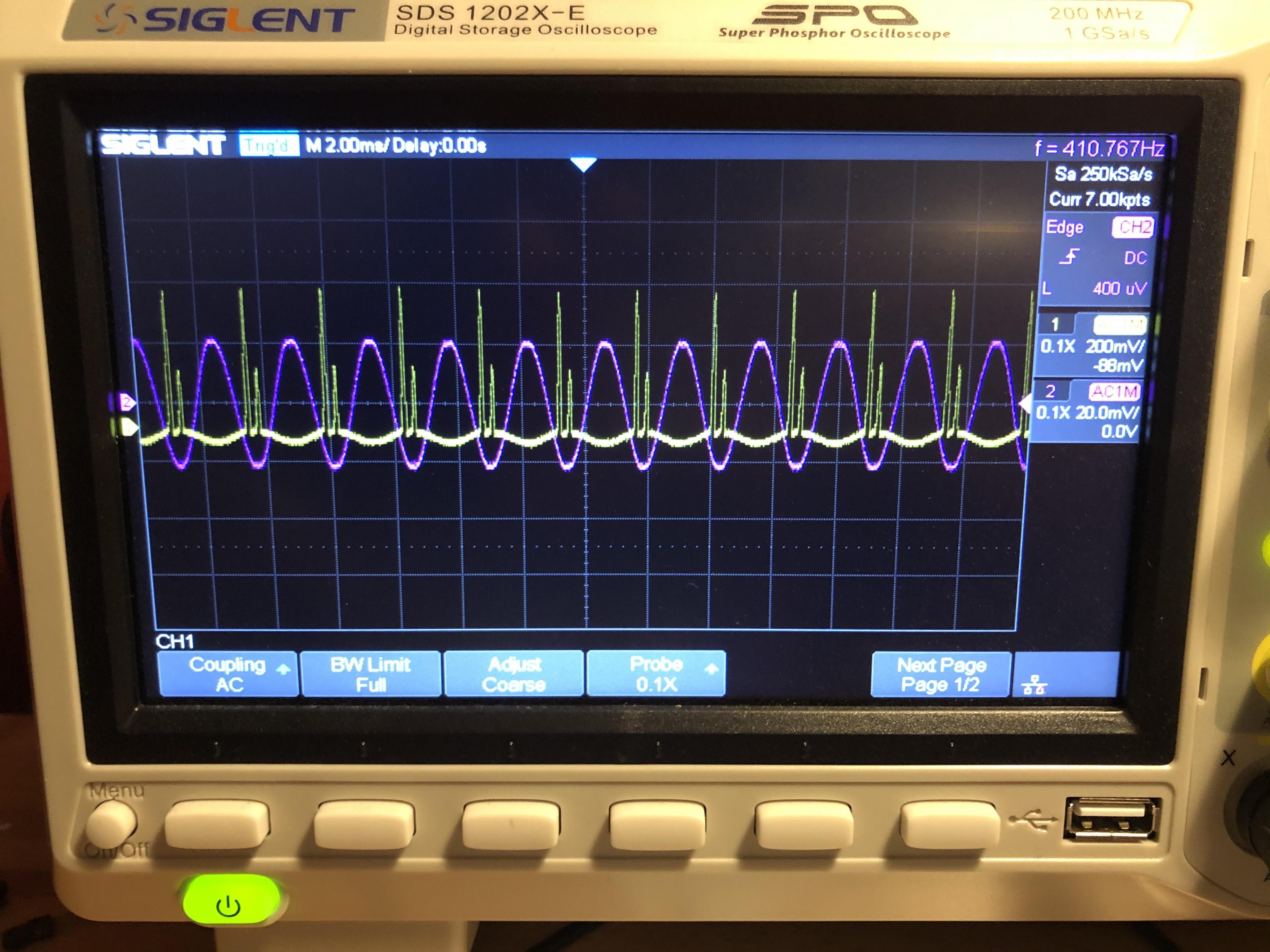
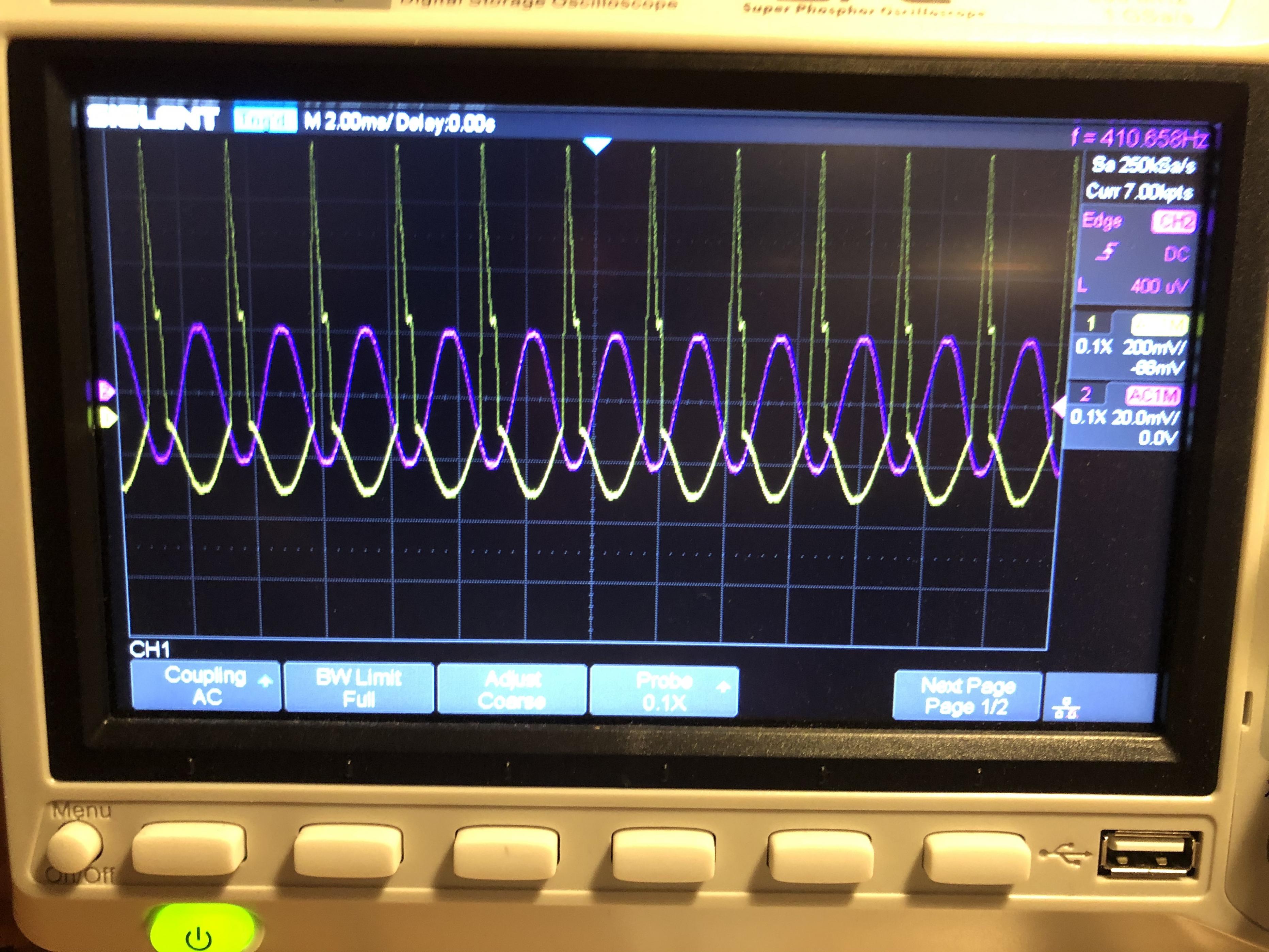
Here's what I'm seeing on the scope. Purple probe is at the input, yellow is at the output side of C5. So you don't have to squint: input scale is 20mv/div, output is 200mv/div, frequency is (a little lower than I was aiming for) ~410hz.
First, with the volume low:

And with the volume near full:

Looking at it now, it seems clear the noise is on the upper part of the output waveform, which makes me wonder if something might be going wrong with/near Q4.
Here's what I'm seeing on the scope. Purple probe is at the input, yellow is at the output side of C5. So you don't have to squint: input scale is 20mv/div, output is 200mv/div, frequency is (a little lower than I was aiming for) ~410hz.
First, with the volume low:
And with the volume near full:
Looking at it now, it seems clear the noise is on the upper part of the output waveform, which makes me wonder if something might be going wrong with/near Q4.
Line power in: fuse first then switch.
R1, R2 go right to ground.
Now that you mention it, I'd remove (as in take out and throw away) C6.
Yeah, don't worry, I didn't install the death cap, moved the fuse to before the switch, 3-prong cord, etc.
Now that you mention it, I'd remove (as in take out and throw away) C6.
Ok, I suppose you are testing this without a load, as asked to.Okay, I added the Zobel and Q3 BE resistor. No major improvement in the sound. Reading about why they're used was educational, though.
Here's what I'm seeing on the scope. Purple probe is at the input, yellow is at the output side of C5. So you don't have to squint: input scale is 20mv/div, output is 200mv/div, frequency is (a little lower than I was aiming for) ~410hz.
First, with the volume low:
And with the volume near full:
Looking at it now, it seems clear the noise is on the upper part of the output waveform, which makes me wonder if something might be going wrong with/near Q4.
Output waveform with good signal injected and volume up is *impossible* so there is some gross wiring error involved.
1) confirm signal injected at input jacks (any of them), is it shown as some 41mVpp so actual 410mVpp because of the 0.1X probe?
Y/N
2) set scope input coupling to AC
Set volume to 10/Max
Lift left end of C3, the one touching Q1 Collector
Scope Q1 collector signal
Post screen capture.
3) scope still DC coupled
Inject your 410mVpp signal on C3 free end (right side still connected to Q2 base)
Scope left side of C3 and show screen capture
Scope right side of C3, same thing.
Scope Q2 base
Scope Q2 emitter
Q2 collector
Q5 base
Q4 emitter
Q5 emitter
C5 left terminal (+), straight at capacitor leg, not the PCB or whatever you used
C5 right terminal (-), again straight at leg.
Junction R15-R18
Speaker out hot terminal.
In all cases, scope and post screen capture.
We are using AC coupling so we do not need to adjust to wildly changing DC levels (which we already checked were reasonably good).
As you see, we are following the breadcrumb trail, to see *where* we lose signal.
I suspect a bad solder, bad homemade PCB, a broken leg component leg, something like that, NO WAY you do not have clean signal at the output except it does not reach there, except by parasitic coupling or something.
Are all partys new or you used some recycled component?
Like my Mechanic always says: "if you have compression, spark and gasoline, your engine MUST start"
Sputtering, putting out white or black smoke, whatever, but it MUST.
Yours is not 😕
Last edited:
Okay, first let's clear up some potential confusion. I should have specified: the results I posted were with an 8R load — I see now that you'd asked for both.
And, in answer to your question #1, the input signal was about 40mVpp, probe is 1X. 410hz was the frequency of the signal.
Here are results with no load (meaning, no speaker or dummy load connected — I suppose R18 and the Zobel are acting as a load...). Note that while input scale remains 20mV/div, output scale is now 1V/div.
With volume at zero, there's some noise:

Here's volume around mid-way, so you can see how clipping begins:

And here's max volume:

I'll work on getting the other measurements as I have time today.
And, in answer to your question #1, the input signal was about 40mVpp, probe is 1X. 410hz was the frequency of the signal.
Here are results with no load (meaning, no speaker or dummy load connected — I suppose R18 and the Zobel are acting as a load...). Note that while input scale remains 20mV/div, output scale is now 1V/div.
With volume at zero, there's some noise:
Here's volume around mid-way, so you can see how clipping begins:
And here's max volume:
I'll work on getting the other measurements as I have time today.
2) set scope input coupling to AC
Set volume to 10/Max
Lift left end of C3, the one touching Q1 Collector
Scope Q1 collector signal
Post screen capture.
This one is quick and easy. Signal looks pretty nice at max vol on Q1 collector with C3 lifted (note output scale is 200mv/div — and oops, I lazily didn't zero the vertical offset):

Last edited:
Ok, so far so good.
Q1 is showing about 10X gain and "almost" perfect sinewave although some clipping is starting to appear on top.
I have a doubt on your scope scale: both to the left of "20.0mV - 200 mV - 1.00 V" scale indications , it shows "0.1X"
WHY?
I thought it meant you were using a 0.1X probe, hence my estimation of 410mVpp input signal.
I am NOT talking frequency.
Is that so?
or: do you have a 0.1X attenuator engaged?
I want to be CERTAIN about scope scale, so far I am not.
At bottom it says: "probe 0.1X"
Please explain that.
That would modify readings by a factor of 10; unless we have that clear , measurements are MEANINGLESS.
Last edited:
Okay, some progress! You were right JMF, there was a bad connection somewhere. While trying to take additional measurements, I noticed a drastic change when I jiggled something. After reflowing every solder joint that looked even a little bit suspicious and doing a little percussive testing to make sure I got it, results measured at output (C5 pos) with no load (other than R18 & the Zobel) look very much better.
Min vol:

Max vol:

Testing with a load, the output looks quite different (this is with a speaker connected, and volume at maybe 3 or 4 — a dummy load looks somewhat similar):

And unfortunately, plugging a guitar in, I'm still hearing pretty much the same distortion as always. So, very bad behavior during measurement is resolved, but the primary issue remains.
Min vol:
Max vol:
Testing with a load, the output looks quite different (this is with a speaker connected, and volume at maybe 3 or 4 — a dummy load looks somewhat similar):
And unfortunately, plugging a guitar in, I'm still hearing pretty much the same distortion as always. So, very bad behavior during measurement is resolved, but the primary issue remains.
- Home
- Live Sound
- Instruments and Amps
- Diagnosing a simple transistor guitar amp