Determine the impedance & winding ratio of a bad output transformer - Help Request
Hi guys,
I'm glad I have some familiars to share amp stuff with.
I have a push/pull OT for a pair of 6CA7/EL34'S. I found an oscillation in a Laney Guitar Tube Amp, and tracked it to the OT with the help of an oscilloscope. One of the primary leads, when hitched to a signal generator, produced a messy screen, while the other was a clean sine wave. Input Signal was set at 7V p/p. I also checked the DC resistance of each primary lead to the CT, and found that they were WAY off.
I am wondering what the next steps to take would be, in determining the primary impedance of this transformer, so that I can ship it out and have a manufacturer rewind it. For a bonus question, if a GOOD output transformer has multiple taps on the secondary side, would I use (1) or all (3) taps to determine the impedance(s), for the sake of having information to send to the shop? Thanks.
I have thought about looking up the EL34's in a tube reference manual, to learn what impedance they would like to see. Not a bad idea, for my technical growth. Using this information, I could safely figure a winding ratio that should match the application. In doing so, am I taking the long way or the short way to complete a repair?
In what way is the resistance "way off" ? What _is_ the resistance center tap to
each anode ? How is the secondary ?
And what current is drawn in the el34 tubes ?
I would examine other possibilities before sending the transformer off. And i would
get a new one, test with that one ( with the possibility to sell the new if the problem stays).
each anode ? How is the secondary ?
And what current is drawn in the el34 tubes ?
I would examine other possibilities before sending the transformer off. And i would
get a new one, test with that one ( with the possibility to sell the new if the problem stays).
Applying say 5VAC to 12VAC from a power transformer secondary to one of the PP half windings, and then measuring the AC voltage on the secondary windings, and on the other half-primary winding, should identify an internal winding short circuit problem. Swap the signal source to the other half-winding to cross-check. Measurements of the applied signal voltage and the voltage on the other half-winding should be quite close, and are normally a little different due to excitation current in the driven half-winding.
If that doesn't show up a problem, and you have no markings to go by, then you can move to trying to deduce the nominal impedances of the windings - ie. from turns ratio's and likely speaker and tube-related impedances. If there is an internal problem due to shorts, then you can't easily use the turns ratios to determine impedances from which to get a new transformer made.
If there is a problem, and one half-winding has a substantially lower resistance, then you may be able to identify if the likely shorted windings are accessible - eg. if they are on the outer layers of the windings, compared to buried within inner winding layers.
Last edited:
In what way is the resistance "way off" ? What _is_ the resistance center tap to
each anode ?
Attachments
Are you Sure that you are measuring to the CT...?
Strange/suspicious that the resistance of one half--is nearly Double that to the other.....
Almost looks as though you are measuring from one half to CT then from one half to the other half--and not to the CT.
Strange/suspicious that the resistance of one half--is nearly Double that to the other.....
Almost looks as though you are measuring from one half to CT then from one half to the other half--and not to the CT.
Alastair E, I just passed the bench again, wondering if I goofed. 😕 That definitely could happen this long after having worked on the project. The total resistance from the blue to red wire is 87.7 ohms. Total from red to black is 58.7 ohms. From blue to black, 29.1 ohms. The blue and red wires were the two attached to the plates.🙂
At 110V, the plate potential is about 405V, the Screen at 404V, and the Control grid at -40V. I'm restarting this project, so most of the data is from a few months ago. I have an eight pin socket already wired up for bias testing... after the output transformer is resoldered back into the amp, the tube current will be tested. Probably tomorrow.
Not Sure at the Moment.And what current is drawn in the el34 tubes ?
At 110V, the plate potential is about 405V, the Screen at 404V, and the Control grid at -40V. I'm restarting this project, so most of the data is from a few months ago. I have an eight pin socket already wired up for bias testing... after the output transformer is resoldered back into the amp, the tube current will be tested. Probably tomorrow.
No real problem here, the winding could be done in one operation, and the
innermost ( that has equally many turns) is shorter.
The importent is what AC impedance one can measure.
As suggested, disconnect the transformer from stuff ( i guess it's enough to
disconnect the center tap), inject a small AC on the secondary ( 6.3V from
filament will do just fine) and measure the AC between center tap and the
two endpoints.
Also try to figure out how much current the 6.3V draws, more then a small numbers of watt dissipation ( > 1A AC ) is a sign of trouble.
If not, seek the problem at other places.
I like the 6.3V test idea, as that is an easy voltage to produce, but the Output Transformer doesn't have a filament winding. This particular transformer has a "tube A", center tap (black lead), and "tube B" on the primary side. On the secondary, four leads exist. The amp has a 3-position switch to choose the correct load impedance that the transformer will see. You can select 4, 8, or 16 ohm.
If I'm asking a correct question here, which two leads from the secondary side can a known voltage be inserted into, in order to produce some usable information about the primary side? Can I learn anything about the specified (intended) primary windings as a whole, just by measuring across the one assumed good half (red to black)? The red-black lead combo, when used for the oscilloscope test, with 7 or so volts applied to them, produced a clean sine wave output across my 8 ohm dummy load. That is why I believe I may have one-half of a good primary side to deduce the total primary windings/winding ratio/impedance ratio.
If I'm asking a correct question here, which two leads from the secondary side can a known voltage be inserted into, in order to produce some usable information about the primary side? Can I learn anything about the specified (intended) primary windings as a whole, just by measuring across the one assumed good half (red to black)? The red-black lead combo, when used for the oscilloscope test, with 7 or so volts applied to them, produced a clean sine wave output across my 8 ohm dummy load. That is why I believe I may have one-half of a good primary side to deduce the total primary windings/winding ratio/impedance ratio.
Peter, thanks again for the tips on what to look for when measuring current across the filaments, I really like learning stuff like that!
There is a risk with applying 6Vac to an unknown OT secondary, as that may be too much for a small transformer, or one with low ohm sections. Plus you can get very large primary voltages.
You found an oscillation - but how? The output transformer has different resistances in its primary windings - but how is this related?
It may ultimately end up that these things are true and related, but God and the Devil dwell in the details.
All good fortune,
Chris
It may ultimately end up that these things are true and related, but God and the Devil dwell in the details.
All good fortune,
Chris
1)
2) you don't need to reinvent the wheel from scratch; IF a new transformer is needed, any "50W 2 x EL34 guitar output transformer" will do, think aftermarket replacements for Marshall,etc.
There's tons to choose from, just don't waste money on expensive Mercury Magnetics; Classictone or Hammond (transformers, not the organ makers) or Weber .... etc. will do just fine.
Marshall 50W Output Transformer for Plexi, JMP and JCM800, 784-139
Hammond Mfg. - "Classic" Push-Pull - Tube Output Transformers - (1608 - 1620, 1645 & 1650 Series)
Output transf. Marshall 50W for JCM900/200 etc. - Output Transf. for
Ausgangsübertrager für Marshall 50W, 2x EL34, 4+8+16 Ohm - Ausgangsü.
British Style Plexi/800 50 Watt Output Transformer - Mojotone.com
I warned you 😉 but if you feel like a Millionaire:
Mercury Magnetics - Marshall amp transformers
3)
But there is a much better way to check for winding shorts:
The Super-Secret Transformer Tester
That said, what makes you think you need to replace the OT?
You spoke about an oscillation, didn't you?
That's not a transformer problem !!!!
Poor contact or measurement error, because "if one winding is shorted, ALL windings are" , since all windings are *magnetically* in parallel, because all are wound around the same core.One of the primary leads, when hitched to a signal generator, produced a messy screen, while the other was a clean sine wave.
2) you don't need to reinvent the wheel from scratch; IF a new transformer is needed, any "50W 2 x EL34 guitar output transformer" will do, think aftermarket replacements for Marshall,etc.
There's tons to choose from, just don't waste money on expensive Mercury Magnetics; Classictone or Hammond (transformers, not the organ makers) or Weber .... etc. will do just fine.
Marshall 50W Output Transformer for Plexi, JMP and JCM800, 784-139
Hammond Mfg. - "Classic" Push-Pull - Tube Output Transformers - (1608 - 1620, 1645 & 1650 Series)
Output transf. Marshall 50W for JCM900/200 etc. - Output Transf. for
Ausgangsübertrager für Marshall 50W, 2x EL34, 4+8+16 Ohm - Ausgangsü.
British Style Plexi/800 50 Watt Output Transformer - Mojotone.com
I warned you 😉 but if you feel like a Millionaire:
Mercury Magnetics - Marshall amp transformers
3)
No, what he told you is to apply 6.3V from the filament winding in the power transformer, to an output winding in the OT, for example the 8 or 16 ohms tap.I like the 6.3V test idea, as that is an easy voltage to produce, but the Output Transformer doesn't have a filament winding.
But there is a much better way to check for winding shorts:
The Super-Secret Transformer Tester
That said, what makes you think you need to replace the OT?
You spoke about an oscillation, didn't you?
That's not a transformer problem !!!!
I agree with Juan, if you really need an OT, and I also am not convinced you do, then just use one of many that already exist in the industry. Your 50 watt guitar amp using EL34s driving common speaker impedances like 4,8, or 16 ohms, is no different from the many other brands and models having the same EL34 to common impedance outputs.
Fender, Marshall, whatever.
Fender, Marshall, whatever.
Laney Pro Tube 50, from the Beginning.
Amp turns on. Roughly playable. Owner mentions a weak output power, amp acts funny. Volume seems to swell and retreat, slowly. Other issues include almost no/faint response from the low impedance input (you plug in and can barely hear it).
First step on bench, speaker test confirmed issues. Amp was connected to a scope and signal source. A sine-in did not produce a pure sine-out. I did not document exactly what I saw for some reason, so I will avoid speculation. *
After checking the tubes in a tube tester and tapping them during speaker test, a few screws were removed to look at the circuit board. A toasted cermet power resistor called to the eye. Checked and found a bad electrolytic next to power resistor and bias adjustment. Live voltage test showed that the bias on the power tubes was a good amount off, but screen and plate voltages were alright (409/410V).
During probing (yes with aliens) the preamp tubes directly with a signal generator (capacitor coupled), something weird shows up. For reference, the high Z input goes to V1, while the low Z goes to V2. Injecting into pin 2 (control grid) of the second triode in V2 sounded bad, while probing into pin 3 (cathode 2nd triode) allows audible hum through to the speaker. I suspect that there shouldn't be signal moving from tube cathode to speaker, right?
*About my notes on the scope test, the output waveform was irregular, and I believe the top half had a greater amplitude than the bottom half. I swapped the position of the Power tubes, no difference was made. I can only imagine I must have swapped the preamp tubes around as well, looking for trouble in the phase inverter tube.
Where are things now? I bought a new replacement OT from Laney. Removed the 1981 original and compared the two. Installed the new one into the amp. Now, it has new issues. See my next post for pictures and data.
Amp turns on. Roughly playable. Owner mentions a weak output power, amp acts funny. Volume seems to swell and retreat, slowly. Other issues include almost no/faint response from the low impedance input (you plug in and can barely hear it).
First step on bench, speaker test confirmed issues. Amp was connected to a scope and signal source. A sine-in did not produce a pure sine-out. I did not document exactly what I saw for some reason, so I will avoid speculation. *
After checking the tubes in a tube tester and tapping them during speaker test, a few screws were removed to look at the circuit board. A toasted cermet power resistor called to the eye. Checked and found a bad electrolytic next to power resistor and bias adjustment. Live voltage test showed that the bias on the power tubes was a good amount off, but screen and plate voltages were alright (409/410V).
During probing (yes with aliens) the preamp tubes directly with a signal generator (capacitor coupled), something weird shows up. For reference, the high Z input goes to V1, while the low Z goes to V2. Injecting into pin 2 (control grid) of the second triode in V2 sounded bad, while probing into pin 3 (cathode 2nd triode) allows audible hum through to the speaker. I suspect that there shouldn't be signal moving from tube cathode to speaker, right?
*About my notes on the scope test, the output waveform was irregular, and I believe the top half had a greater amplitude than the bottom half. I swapped the position of the Power tubes, no difference was made. I can only imagine I must have swapped the preamp tubes around as well, looking for trouble in the phase inverter tube.
- After the above had happened, and I replaced the known defective parts, the bias was restored and I ended up probing the output transformer directly through the red and blue leads during a live test. One of the two tests (red side test and blue side test) produced a sine wave-out, and the other produced a minimum of two waves riding together, and of a lower amplitude than the clean sine test. When the amp was off and the caps unloaded, I tested the resistance through:
- 1. The entire winding, red to blue. 87.7R
- 2. The red to black CT. 58.7R
- 3. The blue to black CT. 29.1R
Where are things now? I bought a new replacement OT from Laney. Removed the 1981 original and compared the two. Installed the new one into the amp. Now, it has new issues. See my next post for pictures and data.

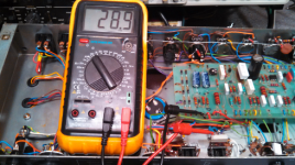
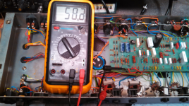
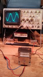
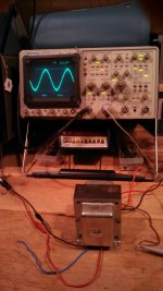
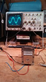
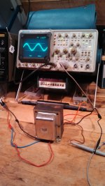
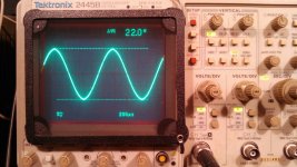
These shots show the different amplitudes across each primary side. The output transformer was bad for this reason alone, although I have suggested (incorrectly) that it was the cause of a low frequency oscillation heard during testing. Does anyone know if there is any truth to this transformer adding "other" problems to the circuit? Wouldn't the load impedance's seen by each power tube be different?
Pictures, from left to right:
Blue/Black lower ohm
Red/Black without cursors adjusted
Red/Black higher ohm
Red/Blue total winding (unnecessary)
Pictures, from left to right:
Blue/Black lower ohm
Red/Black without cursors adjusted
Red/Black higher ohm
Red/Blue total winding (unnecessary)
Attachments
The photos don't identify the test or levels unless you add some extra explanation - the cro screen cursor levels are unclear - the input signal is not defined.
The testing in post #3 is fairly bulletproof and safe, as long as you have a reasonable voltmeter.
The testing in post #3 is fairly bulletproof and safe, as long as you have a reasonable voltmeter.
About the levels...
The test was meant to send an adequate amount of ac through the primary so that a decent signal would show up on the secondary side.
IMPEDANCE QUESTION. The signal generator was maxed out at about 7.48VAC with a 1kHz sine.
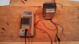
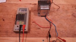
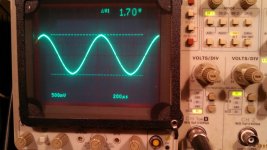
The Fluke 8060A was used for this measurement, and it is a True RMS with no calibration certificate. A Velleman DVM890F read 7.41VAC. I have a question here- The scope is calibrated, performed this year by a well established company near Boston. I understand that it measures peak-to-peak, not rms. IF my connections were all exactly the same impedance, from the generator to the scope input, I would multiply the scope's cursor-to-cursor voltage measurement by .707 to obtain the rms value of a pure sine wave seen by the scope, right? Well, my scope displays a p-p reading of 22VAC when the input is set to 1MEG, and only 1.7VAC when using the 50 ohm impedance input selection. The signal generator has a stated output of 600 ohms. In order to see the correct p-p amplitude on the scope, the generator should have a 600-to-50 ohm impedance modifying bnc on it, and the measurement should be taken using the 50 ohm DC input, right?
The pictures in the previous post compare the amplitude of the red-black portion of the winding to the blue-black section, in a relative way. The new transformer shows 50/51 ohms, on each of the primary sections. I realize this is probably as within tolerance as I will get from a mass produced product, but, would anyone bother to add a 1 ohm resistor??? Even though the resistor will not be the same as an additional turn or two of wire, and it wouldn't contribute to the production of a magnetic field inside the transformer, could it be of any benefit to the system? Thanks.
Pictures, from left to right:
scope w/ 1M input
scope w/ 50 ohm input
The test was meant to send an adequate amount of ac through the primary so that a decent signal would show up on the secondary side.
IMPEDANCE QUESTION. The signal generator was maxed out at about 7.48VAC with a 1kHz sine.
The Fluke 8060A was used for this measurement, and it is a True RMS with no calibration certificate. A Velleman DVM890F read 7.41VAC. I have a question here- The scope is calibrated, performed this year by a well established company near Boston. I understand that it measures peak-to-peak, not rms. IF my connections were all exactly the same impedance, from the generator to the scope input, I would multiply the scope's cursor-to-cursor voltage measurement by .707 to obtain the rms value of a pure sine wave seen by the scope, right? Well, my scope displays a p-p reading of 22VAC when the input is set to 1MEG, and only 1.7VAC when using the 50 ohm impedance input selection. The signal generator has a stated output of 600 ohms. In order to see the correct p-p amplitude on the scope, the generator should have a 600-to-50 ohm impedance modifying bnc on it, and the measurement should be taken using the 50 ohm DC input, right?
The pictures in the previous post compare the amplitude of the red-black portion of the winding to the blue-black section, in a relative way. The new transformer shows 50/51 ohms, on each of the primary sections. I realize this is probably as within tolerance as I will get from a mass produced product, but, would anyone bother to add a 1 ohm resistor??? Even though the resistor will not be the same as an additional turn or two of wire, and it wouldn't contribute to the production of a magnetic field inside the transformer, could it be of any benefit to the system? Thanks.
Pictures, from left to right:
scope w/ 1M input
scope w/ 50 ohm input
Attachments
Your posts are very confusing 🙁 so please just do this:
1) use the new transformer which you just received.
All leads unconnected to anything else, except stated measuring instruments.
2) drive it end to end (red to blue) with your generator, set to 1kHz.
Also connect your scope input across same ends; say ground to blue, hot to red.
FORGET the 50 ohms input, not needed here, just use the 1M setting, also measure end to end voltage with the multimeter.
3) rise the generator output level as much as you can, without getting a distorted signal, then lower it a little to some "round" value, simply for convenience.
Say, if you can get up to 7.48VAC, lower it to plain 7VAC.
VAC measured with the True RMS multimeter, since you have one available.
Leave the other multimeter aside for now, we don't need alternate values at this moment.
4) now measure voltage from center tap (black) to red and to blue, post both values, while still driving the windings end to end .
So: generator still end to end : Red to Blue.
But now Scope ground and multimeter black probe to center tap (black) , and scope hot input and multimeter Red probe measure center to one end, then to the other.
I'm interested in what the multimeter says , simply because it's more precise, the scope is there mainly to confirm that the waveform does not distort or clip and as a rough "backup" meter.
That's enough fo now.
PS: if you wish, you can repeat the exact same tests, but applied to the old supposedly bad transformer, post results in a separate table.
Also measure resistance/continuity from each primary wire to transformer metallic frame/mounting ears/EI sheet stack , both using the diode continuity test scale and a high resistance one, say 20k or so.
Repeat also but from any of 3 primaries to any secondary, which I still trust good.
Sorry for being so obnoxious or nerdy about tests but I see you provide extra data, in good faith of course, which sometimes does not match other results and so confuses the diagnostic.
Thanks 🙂
Last edited:
Perhaps its easier to just use the 8060A for measurement of voltage on each half-primary winding, and the secondary, in order to compare turns-ratios. In that case, remove all other test connections. Also swap the signal input from across blue-blk, to across red-blk, in order to compare results - the turns ratio of the undriven primary half-winding to secondary winding should be the same.
You could connect the cro to the driven half-primary winding prior to above tests to ensure the voltage waveform is a sine. The CRO and meter voltages should be consistent (CRO with 1Meg loading). The largest voltage available that is undistorted should be applied to a half-primary winding.
You could connect the cro to the driven half-primary winding prior to above tests to ensure the voltage waveform is a sine. The CRO and meter voltages should be consistent (CRO with 1Meg loading). The largest voltage available that is undistorted should be applied to a half-primary winding.
- Status
- Not open for further replies.
- Home
- Live Sound
- Instruments and Amps
- Determine the impedance & winding ratio of a bad output transformer - Help Request