Hi,
I´m wondering how to get my two speakers to work together without dropping the resistance too low. My crossover design is in series and its causing the speaker input to drop. I have a tweeter with 4 Ohm and a full range driver with 8 Ohm. I end up with something around 2.3 Ohm. This is way too low for most amplifiers.
Is it any way I can get the resistance higher while still keeping it in series?
Thanx!
If the sensitivity of the tweeter is higher than the full range driver, you could put a padding resistor in line with the tweeter.
Is it any way I can get the resistance higher while still keeping it in series?
Can you post the actual schematic? It sounds more like a parallel crossover.
Last edited:
Done that, but it didn´t change the resistance when i measured it. It might have made the speaker more "amp friendly" which I have no chance of measuring.

My bad, it´s parallel not series as rayma pointed out. Here´s the schematic:
Someone else can simulate this for you, but I'd say there may be an error in the calculations,
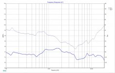
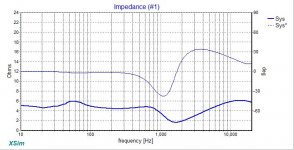
since the time constants are very different. Do you mean the impedance is too low between 1kHz and 3kHz?
Last edited:
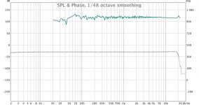
Tweeter wise, wrongly placed Lpads. Put first resistor before the HP, the second one, if you really need one, after the HP and before the HF driver. You can improve impedance by decreasing cap of the HP. Where is the acoustical plots?
First of all what are the nominal impedances of your drivers and their sensitivities ?
From your schematic, the woofer S2 needs to have R4 removed and placed across L1. I presume this is for baffle step compensation.
R3 , what is that for ?
As tweeter sensitivity is usually the higher of the two drivers it is usual to pad its sensitivity down to match the woofer's.
Did you use FRD and ZMA files of your drivers in your 'Xsim' simulation ?
C.M
Tweeter is 4ohm DC sens 3ohm
Woofer 8ohm DC sens 5.7 ohm
I used FRD and ZMA files yes.
R4 is to adjust the slope of the LP, make it softer and trim it at the end.
Woofer 8ohm DC sens 5.7 ohm
I used FRD and ZMA files yes.
R4 is to adjust the slope of the LP, make it softer and trim it at the end.
I did some calculations on the component values in your schematic and it all appears to be wrong. The calculated impedance load for your schematic approximates 2.43 ohms which is about what you have arrived at.
I would suggest you redesign the crossover. You did not state each of the drivers sensitivity in db/ 2.83v/metre but rather each drivers DC resistance, which is a necessary spec. too.
What is your target crossover frequency ?
For instance if you are going to stay with resistor values R1,R2,R3,R4 you would have to change C1 from 3.3uf to 9.24uf , C2 from 30uf to 5.49 uf , L2 from 0.36 mh to 0.94mh.
L1 to remain at 0.56 mh. You would then need to add a series resistor of 1.68 ohms to bring it up to a value of 4 ohms or so. This of course would consume some power but would allow the amplifier to work more safetly with your loudspeaker.
The crossover frequency for this arrangement would be around 2,220 c/s which I am sure the tweeter would be more 'tweeterfriendly'.
Personally I would start again, it all seems rather inefficient ......but then, it is your design.
C.M
Last edited:
I never never saw any attenuation net on the woofer.
Also series crossover is rare, isn't it ?
The schematic of the crossover is at post #5.
C.M
What are the drivers? Your component values do not make much sense. The woofer inductor size tells me you have No bsc. Never place an lpad on the woofer! Not only is that a huge source of the impedance problem, but the resistors will be absorbing a massive amount of power. They will heat up and burn out quickly.
No one has mentioned C2, which looks like the culprit to my uneducated eye.
There are multiple problems here. C2 is just one of them. That cap is basically doing nothing for the tweeter, allowing a lot of energy that the tweeter will probably not handle. It will also have the tweeter playing low so that both drivers are playing the same frequencies over a large area, further contributing to the low imp.
In addition both of the lpads have low values and the lpad on the woofer is totally unnecessary.
- Status
- Not open for further replies.
- Home
- Loudspeakers
- Multi-Way
- Designing crossover series or parallel