Can someone help me out? I was asked to take a shot, but as a couple of members pointed out to me, I am probably not up to the challenge ......
This one didn't meet the requirements as well, but haven't a clue as to why since this is beyond my scope of experience.
http://www.diyaudio.com/forums/showthread.php?
postid=176756#post176756
Anybody?
http://www.discovercircuits.com/A/a-operational.htm
This one didn't meet the requirements as well, but haven't a clue as to why since this is beyond my scope of experience.
http://www.diyaudio.com/forums/showthread.php?
postid=176756#post176756
Anybody?
http://www.discovercircuits.com/A/a-operational.htm
Why would you like to build it? I would help you out, but I'm afraid it's beyond my scope of experience also.
Koinichiwa,
Why on earth would you want to put a Solid State Line Preamp Stage ahead of the "Gainclone"?
I mean WHAT FOR, for crying out loud.
If you MUST have some kind of buffering (there is no need for gain, HONEST) add a buffer. In the easiest a simple Dual J-Fet Follower & Constant current load.
The linestage you referenced was used in conjunction with a Phonostage as a "standalone" preamp.
When using a "Gainclone" As "integrated" Amplifier adding an active preamp stage with gain simply defeats the objective. I know who absolutely, insistently wants an LM6181 Bolted to the front of an IGC, but it absolutely makes NO SENSE.
Sayonara
Fred Dieckmann said:Can someone help me out? I was asked to take a shot, but as a couple of members pointed out to me, I am probably not up to the challenge ......
Why on earth would you want to put a Solid State Line Preamp Stage ahead of the "Gainclone"?
I mean WHAT FOR, for crying out loud.
If you MUST have some kind of buffering (there is no need for gain, HONEST) add a buffer. In the easiest a simple Dual J-Fet Follower & Constant current load.
The linestage you referenced was used in conjunction with a Phonostage as a "standalone" preamp.
When using a "Gainclone" As "integrated" Amplifier adding an active preamp stage with gain simply defeats the objective. I know who absolutely, insistently wants an LM6181 Bolted to the front of an IGC, but it absolutely makes NO SENSE.
Sayonara
Kuei Yang Wang
Then it appears that Peter Daniels earlier suggestion of switching in all the inputs before the pot on the IGC was correct. All we need now is a way to integrate the MM/MC phonostage into the box to make this happen, agreed? Its good to get a corroborative reply from the originator of the LM6181 circuit.When using a "Gainclone" As "integrated" Amplifier adding an active preamp stage with gain simply defeats the objective. I know who absolutely, insistently wants an LM6181 Bolted to the front of an IGC, but it absolutely makes NO SENSE
Koinichiwa,
Yes, of course.
Yes, of course, but then it will not be "6181/IGC", but it will be "IGC" & "El Cheapo Phono".
BTW, IF I where to build something like that myself I would probably keep the 47-labs principle of a seperate Phonostage with seperate supply and an Integrated Amplifier with internal (Shigaraki) or external (Gaincard) source selection.
Alternatively of course we could throw "El Cheapo Phono", "Inverted Gainclone" and "TDA1543 A DAK OF THE CLONES" all into one case, with a fully separated (screened) compartment for the Powersupplies and build and interesting, compact "stereo center" which can take a Turntable (Cartridge) and the Digital Output from a cheap CD Player for the ultimate "DIY PhrugalPhiles" simple system.
Hell, if we could get Scott Nixon on board, he already has Chipamp PCB's, TDA1543 DAC PCB's (all quite affordable), get him to do a "El Cheapo Phono" PCB with a simple 1 BJT Gyrator instead of the Choke in the supply for the MC Stage and we are in Business.
http://www.scott-nixon.com/
(I know REAL MEN only EVER hardwire circuits, but lot's of DIY'ers find PCB's easier)
As Turntable perhaps a tweaked 2nd Hand Technics SL1210 with a Denon DL-103 Pickup and as Player/Transport a Philips CD-723.
Add a pair of Speakers like a pair of the Seas XP Cone Coax in a modest "Minimonitor" Box and a simple Crossover (Capacitor on tweeter and no X-Over on Woofer).
Voila you have simple and good sounding, modest size (3 Boxes incl. Turntable), wife-friendly system. I'd wager the results will be "good enough" for many people.
Hey, this sounds like fun. Maybe a system for my future study (when I have renovated it)?
Sayonara
nania said:Then it appears that Peter Daniels earlier suggestion of switching in all the inputs before the pot on the IGC was correct.
Yes, of course.
nania said:All we need now is a way to integrate the MM/MC phonostage into the box to make this happen, agreed?
[/B]
Yes, of course, but then it will not be "6181/IGC", but it will be "IGC" & "El Cheapo Phono".
BTW, IF I where to build something like that myself I would probably keep the 47-labs principle of a seperate Phonostage with seperate supply and an Integrated Amplifier with internal (Shigaraki) or external (Gaincard) source selection.
Alternatively of course we could throw "El Cheapo Phono", "Inverted Gainclone" and "TDA1543 A DAK OF THE CLONES" all into one case, with a fully separated (screened) compartment for the Powersupplies and build and interesting, compact "stereo center" which can take a Turntable (Cartridge) and the Digital Output from a cheap CD Player for the ultimate "DIY PhrugalPhiles" simple system.
Hell, if we could get Scott Nixon on board, he already has Chipamp PCB's, TDA1543 DAC PCB's (all quite affordable), get him to do a "El Cheapo Phono" PCB with a simple 1 BJT Gyrator instead of the Choke in the supply for the MC Stage and we are in Business.
http://www.scott-nixon.com/
(I know REAL MEN only EVER hardwire circuits, but lot's of DIY'ers find PCB's easier)
As Turntable perhaps a tweaked 2nd Hand Technics SL1210 with a Denon DL-103 Pickup and as Player/Transport a Philips CD-723.
Add a pair of Speakers like a pair of the Seas XP Cone Coax in a modest "Minimonitor" Box and a simple Crossover (Capacitor on tweeter and no X-Over on Woofer).
Voila you have simple and good sounding, modest size (3 Boxes incl. Turntable), wife-friendly system. I'd wager the results will be "good enough" for many people.
Hey, this sounds like fun. Maybe a system for my future study (when I have renovated it)?
Sayonara
IC said the blind man.......
The idea for the thread was from Petter D.
The idea for the LM6181 linestage from the guy that Petter told to start thread to begin with.
The reference was to design that was posted by Kuei Yang Wang
in post number 2 in the Local power regulators.
My only intent was to get this thing out of my yard as the neighbors are starting to complain.
"If you MUST have some kind of buffering (there is no need for gain, HONEST) add a buffer. In the easiest a simple Dual J-Fet Follower & Constant current load."
Kuei Yang Wang,
Now I am confused. Isn't selection of the top 2.2 K resistor a unity gain inverting follower? Is the K170 or the J74 acting as the current source? Why is there a pot on the output? As I said, this is a bit beyond my experience.
"Your Highness is like a......."
That one was Wilde's.
Attachments
FET input
Hi,
I would include source resistors in the above circuit.
Or use two identical FET's in one package like 2SK389 as in fig. 3.29 in Horowitz. Here the lower FET acts as a current source for the upper FET. As Fred points out out I don't see how this is going to work. I mean the biasing of the P- and N-channel FET.😎
Such a simple circuit and people doubting that it works 😕
It does work and it sounds OK. It doesn't need source resistors but a gatestopper resistor is preferred.
I describe the circuit at first sight as a linestage/buffer:
A J-FET follower/buffer ( high imp. in, low imp. out ) that drives a inverting gainstage that can be adjusted for gain if needed or unity gain. The J Fet follower is needed because of the low input impedance of the inverting opamp circuit. 270 ohm input impedance in the worst case is too low for most sources. At the output there is a volume pot for adjusting volume. Very practical in daily life.
We could discuss the need for this circuit as the same opamp could be used in non-inverting mode and the J Fet's wouldn't be needed. I guess TL uses this circuit because the "better sounding" ( not my words ) result of inverting opamp circuits.
FYI Pioneer used this circuit with 2SJ74 and 2SK170 in cdplayers so that they could write "Class A output stage" on the front of their cdplayers.
Re: IC said the blind man.......
Koinichiwa,
!!!????
Okay. I repeat, my main point is that the "Inverted Gainclone" has no need for any form of input buffering. The 6181 Linestage referred to by nania is the one posted in the local reg thread, though the schematic alone does not explain much of the workings. And as mentioned, it lacks some of the actual implemented circuit features.
Yes.
But if it is meant to be used with a gainclone a by far too complex one. The original design is a rather specific type of a "Buffered Passive Preamp".
A little history and context for the Circuit being discussed.
The Volume Control is done after the "buffer" with a switched set of resistors. The Active circuit is meant to present the source with a very high impedance (1 meg in my case - choice was based on Mark Levinsons Cello "1M" Linestage) while providing a very low impedance output on which the Volume can be controlled using a simple "Single Series Single Shunt Resistor" (S4R) attenuator having a very low impedance.
This Preamp design by far predates my current use of "TVC" Passives. Before TVC's became all the rage friends of mine and I as well experimented with various resistive volume controls. We found that reliably the sound improved the lower the impedances where and we found the S4R type attenuator sonically to be best.
So, using a 1K series resistor and suitable shunt resistors sounded great if the source had a really meaty output stage, but we found that any of the more wimpy output stages often found on even "High End" gear (never min valve gear) took exception to such punishing loads.
Plus, with pure passive linestages you often find you are these crucial 6db gain short (hence all the TVC's designed with original input from me have an option for 6db "passive" gain). My answer back then was to use a buffer arranged around a CFB Op-Amp (I know, many people don't like CFB Op-Amps - I fail to understand why) as it can provide substantial voltage swing into a very low impedance loads.
True to my own Mantra and chorus "Op-Amp - Invert Da Suckah" the circuit is inverted, which means we now have a lot of output peak current (around 70mA) available, but the input impedance is still low. The J-Fet buffer (it is Push-Pull) buffers the Input to give a very high input impedance.
In my original design the gain was fixed at 0db BTW and the "build-out" resistor was 100 Ohm, not 300 Ohm. The result is a rather transparent "semi" passive preamp that drives any sort of cables with impunity. Yet while very good, it always struck me as a somewhat cludgy, inelegant and in need of simplification. I generally keep the circuit around and keep refering to it more because of the PSU implemented later (original was 2pcs 12V Lead Acid Batteries and local capacitive decoupling).
Anyway, it is a very specific circuit for a specific application to achieve a specific purpose. Adding this in front of the "Inverted Gainclone"
Most should be clear from the above.
The Input section requires both J-Fets to be selected for identical Idss with 15V applied, I used a 22R adjustable pot in the source lines to null out any remaining offset, the Idss should be around 10mA with a 10 ohm source resistor for the abovementioned arrangement.
This "push-pull" source-follower is a very nice Class A buffer with low distortion (a few V into 1k are < 0.01%), low output impedance in the region of < 30 Ohm and low input capacitance (28pF), plus it's simplicity appeals to me. However, driving the 100R series resistor shunt Volume control made this buffer rather unhappy, showing that really 1k is about the lowest load it should be driving at higher levels.
Does that help? At any extent, this circuit as such is no longer "recommended", other than for educational purposes. A good quality TVC is a much better "linestage".
Sayonara
Koinichiwa,
Fred Dieckmann said:The idea for the thread was from Petter D.
The idea for the LM6181 linestage from the guy that Petter told to start thread to begin with.
The reference was to design that was posted by Kuei Yang Wang
in post number 2 in the Local power regulators.
My only intent was to get this thing out of my yard as the neighbors are starting to complain.
!!!????
Okay. I repeat, my main point is that the "Inverted Gainclone" has no need for any form of input buffering. The 6181 Linestage referred to by nania is the one posted in the local reg thread, though the schematic alone does not explain much of the workings. And as mentioned, it lacks some of the actual implemented circuit features.
Fred Dieckmann said:Now I am confused. Isn't selection of the top 2.2 K resistor a unity gain inverting follower?
Yes.
But if it is meant to be used with a gainclone a by far too complex one. The original design is a rather specific type of a "Buffered Passive Preamp".
A little history and context for the Circuit being discussed.
The Volume Control is done after the "buffer" with a switched set of resistors. The Active circuit is meant to present the source with a very high impedance (1 meg in my case - choice was based on Mark Levinsons Cello "1M" Linestage) while providing a very low impedance output on which the Volume can be controlled using a simple "Single Series Single Shunt Resistor" (S4R) attenuator having a very low impedance.
This Preamp design by far predates my current use of "TVC" Passives. Before TVC's became all the rage friends of mine and I as well experimented with various resistive volume controls. We found that reliably the sound improved the lower the impedances where and we found the S4R type attenuator sonically to be best.
So, using a 1K series resistor and suitable shunt resistors sounded great if the source had a really meaty output stage, but we found that any of the more wimpy output stages often found on even "High End" gear (never min valve gear) took exception to such punishing loads.
Plus, with pure passive linestages you often find you are these crucial 6db gain short (hence all the TVC's designed with original input from me have an option for 6db "passive" gain). My answer back then was to use a buffer arranged around a CFB Op-Amp (I know, many people don't like CFB Op-Amps - I fail to understand why) as it can provide substantial voltage swing into a very low impedance loads.
True to my own Mantra and chorus "Op-Amp - Invert Da Suckah" the circuit is inverted, which means we now have a lot of output peak current (around 70mA) available, but the input impedance is still low. The J-Fet buffer (it is Push-Pull) buffers the Input to give a very high input impedance.
In my original design the gain was fixed at 0db BTW and the "build-out" resistor was 100 Ohm, not 300 Ohm. The result is a rather transparent "semi" passive preamp that drives any sort of cables with impunity. Yet while very good, it always struck me as a somewhat cludgy, inelegant and in need of simplification. I generally keep the circuit around and keep refering to it more because of the PSU implemented later (original was 2pcs 12V Lead Acid Batteries and local capacitive decoupling).
Anyway, it is a very specific circuit for a specific application to achieve a specific purpose. Adding this in front of the "Inverted Gainclone"
Fred Dieckmann said:Is the K170 or the J74 acting as the current source? Why is there a pot on the output? As I said, this is a bit beyond my experience.
Most should be clear from the above.
The Input section requires both J-Fets to be selected for identical Idss with 15V applied, I used a 22R adjustable pot in the source lines to null out any remaining offset, the Idss should be around 10mA with a 10 ohm source resistor for the abovementioned arrangement.
This "push-pull" source-follower is a very nice Class A buffer with low distortion (a few V into 1k are < 0.01%), low output impedance in the region of < 30 Ohm and low input capacitance (28pF), plus it's simplicity appeals to me. However, driving the 100R series resistor shunt Volume control made this buffer rather unhappy, showing that really 1k is about the lowest load it should be driving at higher levels.
Does that help? At any extent, this circuit as such is no longer "recommended", other than for educational purposes. A good quality TVC is a much better "linestage".
Sayonara
Re: IC said the blind man.......
To be accurate, it was not idea from me, but rather my advice to nania how to properly formulate thread titles to get wanted response. And response he got, and now he knows almost everything about his integrated amp approach.
Of course, Fred wanted to be melodramatic and couldn't miss another opportunity for sarcasm.
Fred Dieckmann said:The idea for the thread was from Petter D.
To be accurate, it was not idea from me, but rather my advice to nania how to properly formulate thread titles to get wanted response. And response he got, and now he knows almost everything about his integrated amp approach.
Of course, Fred wanted to be melodramatic and couldn't miss another opportunity for sarcasm.
My goodness guys ,shake each other hands and lets get over it!
This is not Jerry Springer show.LOL.
Cheers.🙂
This is not Jerry Springer show.LOL.
Cheers.🙂
Koinichiwa,
Good thing too. Their security is way too tight for my taste.
I still believe in perpetuating my viewpoint by shooting all opponents, if neccesary twice.
(for the inhabitants of the United States of a part of Oliver North America - sarcasm alert - yes, it's meant to be funny - so laugh)
Sayonara
HighTec said:My goodness guys ,shake each other hands and lets get over it!
This is not Jerry Springer show.LOL.
Good thing too. Their security is way too tight for my taste.
I still believe in perpetuating my viewpoint by shooting all opponents, if neccesary twice.
(for the inhabitants of the United States of a part of Oliver North America - sarcasm alert - yes, it's meant to be funny - so laugh)
Sayonara
I used to rather enjoy Jerry Springer show, when it first came out. Later, it got boring. I don't mind some excitement from time to time, as long as everybody's enjoying it.😉 There are of course, always, some over sensitive types, and then the show has to end.
Hey Keui,
Are you still game on a matter we discussed some time ago? It would be interesting to come up with a nice speaker design for all those folks building GainClones.😉
Hey Keui,
Are you still game on a matter we discussed some time ago? It would be interesting to come up with a nice speaker design for all those folks building GainClones.😉
Koinichiwa
Yes I'm game. In fact, I'm so gamey, it smells two blocks.....
However, I'm kinda short on time. It's on the backburner. I have started, but it needs more work.
to make it simple, take the driver discussed, place it in a small sealed box (say 10l) and use a simple, single capacitor (say 2u2 - good quality please). That should make for a pretty affordable nice sound (and simple - in classic Gainclone manner).
Now ME PERSONALLY - I'd be tempted to make the box according to the golden mean and from solid, soft "Klang Holz" Spruce or pine. BWTFDIK.
Of course, there is by far more potential in this driver if you go:
1) Active
2) Current Drive
3) Subtractive Cossovers
But even so, I suspect a small Monitor with that specifc coax, keeping the "Woofer" part running wide open as "wideband" will work great. The seemingly way too small capacitors offsets the tweeters raised upper midrange (compared to medium and high treble) and rolls in the tweeter gently where the woofer rolls of naturally.
I get back (in public) when I have time for the active, subtractive crossover, current drive version. It is near completion, except I have yet to find a way to combine the tweeter EQ with the rest without adding more active circuits.
So far I have a J-Fet Buffer and the two pcs LM3875 forming the "current drive" Amplifier, inverting 3rd order Highpass, LF Driver EQ for current drive with the buffer making sure our filter see a constant source impedance.
I suppose one can always place the HF EQ ahead of the buffer (or maybe after), but that would be cheating. I'll of course chaet if I have to.
Sayonara
PS, we wish to hold the world, but our brains are not yet world sized (except on the morning after serious drinking - and then the size does not help)
Peter Daniel said:Hey Keui,
Are you still game on a matter we discussed some time ago? It would be interesting to come up with a nice speaker design for all those folks building GainClones.😉
Yes I'm game. In fact, I'm so gamey, it smells two blocks.....
However, I'm kinda short on time. It's on the backburner. I have started, but it needs more work.
to make it simple, take the driver discussed, place it in a small sealed box (say 10l) and use a simple, single capacitor (say 2u2 - good quality please). That should make for a pretty affordable nice sound (and simple - in classic Gainclone manner).
Now ME PERSONALLY - I'd be tempted to make the box according to the golden mean and from solid, soft "Klang Holz" Spruce or pine. BWTFDIK.
Of course, there is by far more potential in this driver if you go:
1) Active
2) Current Drive
3) Subtractive Cossovers
But even so, I suspect a small Monitor with that specifc coax, keeping the "Woofer" part running wide open as "wideband" will work great. The seemingly way too small capacitors offsets the tweeters raised upper midrange (compared to medium and high treble) and rolls in the tweeter gently where the woofer rolls of naturally.
I get back (in public) when I have time for the active, subtractive crossover, current drive version. It is near completion, except I have yet to find a way to combine the tweeter EQ with the rest without adding more active circuits.
So far I have a J-Fet Buffer and the two pcs LM3875 forming the "current drive" Amplifier, inverting 3rd order Highpass, LF Driver EQ for current drive with the buffer making sure our filter see a constant source impedance.
I suppose one can always place the HF EQ ahead of the buffer (or maybe after), but that would be cheating. I'll of course chaet if I have to.
Sayonara
PS, we wish to hold the world, but our brains are not yet world sized (except on the morning after serious drinking - and then the size does not help)
On a backburner for a while is fine, as I also have some projects to finish, but not too long😉.
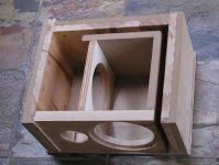
The box definitely has to be out of solid wood. This one is made of 3/4" maple plank, used for floors with MDF on the outside. I find that with time, wood tends to warp and MDF is there to keep the panels straight. The sides however, will be solid maple boards, like Sonus Faber. Again, the woofer, 5" AudioTechnology, is connected straight to the the amp, no crossover and a single cap on Triangle tweeter.
I will start lookin for those Seas drivers.
Attachments
- Status
- Not open for further replies.
- Home
- Amplifiers
- Solid State
- Designing 6181/IGC integrated amp: help needed