We had designed a 10W JLH class-A amplifier a few weeks before. The result is very positive. Now a lot of diyaudio members begin to make their JLH amp with the free PCB we offered.
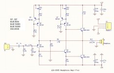
We are planning to design another JLH project- The headphone amplifier. The circuit is similar with the 10W JLH, but the values and part no are different. Unlike the 10W JLH need 2A quiscent current, 200 to 300mA is enough for a headphone amplifier. +-12V will be more than enough for driving any headphone. So MJE15003 is used instead of MJ15003, BC550 takes the place of BD139 and BC560 for BD140. The schematic and PCB are attached. If there's any suggestions please feel free to let me know.
We are planning to design another JLH project- The headphone amplifier. The circuit is similar with the 10W JLH, but the values and part no are different. Unlike the 10W JLH need 2A quiscent current, 200 to 300mA is enough for a headphone amplifier. +-12V will be more than enough for driving any headphone. So MJE15003 is used instead of MJ15003, BC550 takes the place of BD139 and BC560 for BD140. The schematic and PCB are attached. If there's any suggestions please feel free to let me know.
Attachments

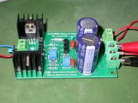
Built and tested!
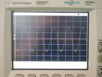
The boards fab out yesterday, I tested today...setting the Iq to 250ma, input 1KHz -30dBV signal, 600Ohm load, the the THD is only 0.008%! Listen with my HD600 the sound is awesome!!!
The boards fab out yesterday, I tested today...setting the Iq to 250ma, input 1KHz -30dBV signal, 600Ohm load, the the THD is only 0.008%! Listen with my HD600 the sound is awesome!!!
Attachments

Last edited:
I have fond memories of the JLH amp - built 6 of them to power a three-way KEF speaker system. Would be interested in the head-phone amp - looks like the design is not so bad for sourcing parts.
You may want to dig up the big JLH thread. A JLH does not require fancy parts at all, quite the contrary. 2N/PN2907, 2N/PN2222 and TIP31C/TIP41C will do fine. It also likes 2N5551, MPSA18 and BC639 in the splitter (hmm... a preference for good VAS transistors perhaps?) and 2N5401 in the current source, at least in simulation with the models I have... Apparently there's some cancellation going on between the current source and splitter. The input transistor seems to be reasonably noncritical, the usual suspects like BC557-560 work fine, as again does a 2N5401.
Apparently there is some sort of distortion cancellation going on in the splitter and output stage when driving high-impedance loads. If I put in a complementary output stage it becomes better for lor-impedance loads but worse for high-impedance ones.
This variation of the circuit is interesting, it sure does away with a bunch of bulky 'lytics. Seems to be more prone to oscillation though, possibly as a result of the input current source. Once I did away with the parallel RC in the feedback, the basic JLH seemed stable even with no output series resistance.
All that being said, an opamp-based circuit with a discrete AB buffer may be the more attractive proposition in terms of parts count and performance these days.
- Status
- Not open for further replies.