I'm working on a Denon DP-37F that's exhibiting a strange intermittent issue: Sometimes it spins forward and the speed locks to the quartz reference, and then other times it will only spin slowly backwards (CCW). All of the power supply voltages check out when the table is misbehaving. I've gone over the boards several times looking for bad solder joints and touched up several. I've tried prodding areas of the boards with an insulated stick and applying heat to either induce or abate the issue. I've also replaced all of the electrolytics around the arm and motor control IC's.
My understanding is that the slow backwards spinning is the motor getting a signal to brake. According to the datasheet for the motor controller IC, which is a TC9142P, the reverse signal for braking is output from pin 9, however that pin is unused in the DP-37F application. Understanding how braking is accomplished might help me narrow down where to focus my troubleshooting efforts. Or if anyone has other thoughts, I'm all ears. @Mooly 🙂

My understanding is that the slow backwards spinning is the motor getting a signal to brake. According to the datasheet for the motor controller IC, which is a TC9142P, the reverse signal for braking is output from pin 9, however that pin is unused in the DP-37F application. Understanding how braking is accomplished might help me narrow down where to focus my troubleshooting efforts. Or if anyone has other thoughts, I'm all ears. @Mooly 🙂
I've seen less circuitry in some VCR's 😉
I would look at what the control voltage to hall effect motor does (voltage on R201) to see if that gives any clues. You will have to determine what the expected voltages are when its running normally and load the platter by hand to see what the voltage does to get an idea of which way the voltage goes to increase speed. Then compare when its faulty.
It could be many things, something like an intermittent O/C drive transistor or even one of the Hall sensors on the motor. Also look at the signal on C6 which is the feedback from the speed sensor coil.
Well, the worst thing possible happened when troubleshooting an intermittent: I appear to have solved the problem without figuring out the cause. 🙄
I couldn't get the table to run normally in order to measure the control voltage and see the feedback signal on my scope. So I tried some hot air again, but warmer than last time (250 degrees F or so). I aimed it at the motor drive transistors (TR01 - TR04), followed by IC201, IC8, and then IC1. Using a 5mm nozzle on my heat gun, it was fairly well targeted. It appeared that after warming IC1, the table began to spin normally. This was yesterday, and it's still working normally today. Up until now, it would have acted up again by this point. I'm hoping that it will misbehave again so that I can re-test the affect of the heat on IC1. I suppose I could try some freeze spray.
Here are the voltages I measured at R201.
Abnormal operation, power on (not spinning): -0.17V
Abnormal operation, power on (spinning CCW): -0.80V
Normal operation, power on (not spinning): +.075V
Normal operation, power on (spinning CW): +1.0V
I didn't get to check the signal at pin 6 of IC1 during abnormal operation (there was something wrong with my probe), but, as expected, I saw a clean square wave during normal operation, platter spinning CW.

It finally acted up again. I heated just IC1, nothing else, while the platter was spinning counterclockwise, and it began rotating clockwise after a few seconds and the quartz lock lit up. I've already re-soldered all of the joints on this. So while I don't like to indict a big IC too quickly, I do think it's the problem here.
It sounds pretty conclusive unless it happened to be a part right up to the chip that was also getting hot. Apply heat to the chip with a soldering iron tip to make sure its local.
Good idea. I just tried that, and the result was the same. I'll working on sourcing a replacement and circle back with confirmation of the fix. Thanks Mooly!
I installed a new IC, but the problem persisted. I assume that I must have heated up something else, despite my care. So. . . looking at the area (and the schematic) again, the crystal is the closest component that would explain the issue. I used a much lower temp on my soldering iron, and holding it just over the crystal was able to induce the table to spin normally.
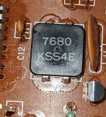
This is a 7.68MHz crystal (see attached photo). The particular package isn't available at Mouser or Digikey, though that doesn't matter since two of the four legs are just for mounting purposes, and I'll have enough clearance for one of the taller types that are currently available. What other electrical characteristics should I consider when choosing among the options, e.g. load capacitance and ESR?
This is a 7.68MHz crystal (see attached photo). The particular package isn't available at Mouser or Digikey, though that doesn't matter since two of the four legs are just for mounting purposes, and I'll have enough clearance for one of the taller types that are currently available. What other electrical characteristics should I consider when choosing among the options, e.g. load capacitance and ESR?
Attachments
I suppose it could be the crystal... what about the two 10pF caps. Are they SMD parts under the crystal? Have you reflowed the crystal and caps?
Interesting but I wouldn't get to hung up on this:
https://www.avnet.com/wps/wcm/conne...als.pdf?MOD=AJPERES&CVID=nP2o81d&CVID=nP2o81d
The oscillator on the chip will just be a basic CMOS invertor like the first image in the link above and they drive the crystal hard and should work with pretty much anything.
Those two 10pF caps are both regular through-hole ceramics, maybe about 8mm away. I didn't re-flow them, but I did do the crystal (no change). I'll try to eliminate the caps from suspicion before moving forward on ordering the crystal.
Rigging up the scope on the oscillator output pin might tell you a lot. If the fault occurs and it is the crystal or caps then the signal there will show a problem.
I didn't end up replacing the crystal. Instead I went back over that area of the PCB with magnification yet another time. I found that the solder pad for pin 3 of IC1 (connecting to one side of the crystal) was almost invisibly separated from the trace. After fixing this the table has operated without a hitch for four days straight of testing. I'm guessing that when I applied heat it was causing the copper to expand just enough to bridge the gap.
thanks for sharing. i'm the happy original owner of a denon dp-37f purchased new back in the 1980s. these fault discovery and repair tips for the future are extremely useful.
- Home
- Source & Line
- Analogue Source
- Denon Turntable Intermittent Issue