I got this Denon DCT-R1 for around $250 in hope I could repair it. It has audio signal out of the RCAs, but not out of the high level output. It has a HA13150A for the "amp" and it appears to me that pin 2 is grounded (or not getting its 3.5+ volts) and is in standby mode.
I have traced Pin 2 as best I can. It goes (from the amp backwards) to a small capacitor (I assume to smooth out voltage ripples) and also through a 000 SMD resistor, which leads to a small SMD device with the marking MB. That device has one leg on a pad that leads to nothing, so I'm assuming its used to secure it, another leg connected through the 000 resistor, and the last leg going out to a few resistors (which have their other side on a ground circuit) and another unknown device with the marking 13(28 sideways).
The 13-28 device has 5V on its one leg, which passes through to the other leg on the same side. The leg on the opposite side is the one that goes through to the resistors and MB smd device. If I jump across it, giving 5 volts to the MB device and resistors, I get audio output.
I have found 3 other 13-28 devices. 2 of them have 5 volts on the same legs and nothing on the opposite leg. 1 of them has 12 volts on the leg that has 5v on the other devices, but that one allows the 12 volts to travel across the device and it does not jump from leg to leg on the same side.
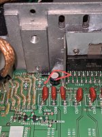
I'm sorry for the poor description, but I don't know what the devices are so I can't number the legs appropriately. I've included a picture that shows the pin 2 travel (red), as well as where ground (black dot) is, and where my 5v is (green).
The cd not ejecting seems to be a belt, so I have one ordered, but I'd really like to get the audio working...even though I will probably use it through the RCAs regardless.
I have traced Pin 2 as best I can. It goes (from the amp backwards) to a small capacitor (I assume to smooth out voltage ripples) and also through a 000 SMD resistor, which leads to a small SMD device with the marking MB. That device has one leg on a pad that leads to nothing, so I'm assuming its used to secure it, another leg connected through the 000 resistor, and the last leg going out to a few resistors (which have their other side on a ground circuit) and another unknown device with the marking 13(28 sideways).
The 13-28 device has 5V on its one leg, which passes through to the other leg on the same side. The leg on the opposite side is the one that goes through to the resistors and MB smd device. If I jump across it, giving 5 volts to the MB device and resistors, I get audio output.
I have found 3 other 13-28 devices. 2 of them have 5 volts on the same legs and nothing on the opposite leg. 1 of them has 12 volts on the leg that has 5v on the other devices, but that one allows the 12 volts to travel across the device and it does not jump from leg to leg on the same side.
I'm sorry for the poor description, but I don't know what the devices are so I can't number the legs appropriately. I've included a picture that shows the pin 2 travel (red), as well as where ground (black dot) is, and where my 5v is (green).
The cd not ejecting seems to be a belt, so I have one ordered, but I'd really like to get the audio working...even though I will probably use it through the RCAs regardless.
Attachments
Have you tried getting the service manual from Denon or pacparts?
The following page will help find SMD part numbers. There are multiple parts using the same markings so you have to narrow it down by package, etc.
Marking smd
If a 3 terminal device has only two legs used, it's generally a diode.
The following page will help find SMD part numbers. There are multiple parts using the same markings so you have to narrow it down by package, etc.
Marking smd
If a 3 terminal device has only two legs used, it's generally a diode.
Last edited:
I emailed Denon, have not heard back yet. Pac parts does not list this model, or at least not that I can find.
I forgot to mention, the SMD device marked MB is not in the picture, I had it removed. It is connected where the red dot is, the open pad to the left, and just below the white dot.
Also, apparently you have to call Pac so I'll give them a jingle tomorrow.
Also, apparently you have to call Pac so I'll give them a jingle tomorrow.
Called pac parts, and they said the service manual has been discontinued... didn't know that was a thing.
You can request models that aren't listed as being available here:
PDF service manuals for Whirlpool, Maytag, Samsung and more
Help me! Need a manual! | Elektrotanya
Are there any clones of this head unit?
PDF service manuals for Whirlpool, Maytag, Samsung and more
Help me! Need a manual! | Elektrotanya
Are there any clones of this head unit?
No one anywhere has one. I tried finding another deck/diagram that uses the same amplifier but I can't come up with anything. I'm going to try pulling off all 3 of the similar marked transistors, testing them, and seeing if they all function the same. Not sure what else I can do yet... going to wait until the weekend when I have more time and my hot air station comes in.
Worst case scenario, disconnect the drive to the IC and install a switch to control it.
Hot air rework stations can cause more problems than they solve. What is it that you can't do with a standard soldering iron?
If the internal amp is controlled through the micro-controller, I'd be careful. One slip when working with the pins on the micro-controller can brick the whole unit.
Hot air rework stations can cause more problems than they solve. What is it that you can't do with a standard soldering iron?
If the internal amp is controlled through the micro-controller, I'd be careful. One slip when working with the pins on the micro-controller can brick the whole unit.
I'm staying away from the micro controller as best I can. Getting a hot air station because I'm trying to get better quality smd soldering. When would the amplifier even need to be in standby, simply when the unit is muted or in powered off when the key is on?
The hot air applies too much heat to the body of the component and to adjacent components.
Remove all solder from all pads. Apply new solder to one pad. Using tweezers, place the component and heat the solder so that the component drops to the pad. Adjust if necessary. Then solder the remaining pads. Clean flux with acetone or alcohol and cotton swabs.
Remove all solder from all pads. Apply new solder to one pad. Using tweezers, place the component and heat the solder so that the component drops to the pad. Adjust if necessary. Then solder the remaining pads. Clean flux with acetone or alcohol and cotton swabs.
Perry, when would the amplifier even need to be in standby, simply when the unit is muted or in powered off when the key is on?
I don't know what benefit there would be to have the IC disabled. For some ICs, it could reduce the operating temperature slightly for head units that tend to overheat. The ICs shouldn't have much bias current but the ICs often have so much gain that they clip hard when more than 1/2 of the volume control's range is used. That hard clipping could cause heating or could possibly produce noise on the 12v line.
Others may have purchased head units with the ability to shut down the internal amp. Maybe they could tell you what the marketing behind it is/was.
Others may have purchased head units with the ability to shut down the internal amp. Maybe they could tell you what the marketing behind it is/was.
- Home
- General Interest
- Car Audio
- Denon DCT-R1 No Audio No CD Eject