Hi guys,
ages since I'm not asking stupid questions here... Anyway, I've recently got an oldie DCD-980. It was reading CDs very fast and after a quick listening seemed promising.
So I initially looked for some quick&dirty pieces of advice on upgrading Denon players. I clipped off the ceramic caps and muting transistors in the output stage, added a film bypass to the two electrolytic(!) 100u coupling caps, replaced and bypassed the two PSU main caps and liberally beefed up and/or added some local bypass to caps for the power lines.
As of today it plays way better than I thought. The attached schematic (for a single channel) shows the output circuit from the dac to the audio output. The I/V and LPF are made with two halves of a humble NEC uPC4570c op-amp, std low quality resistors and with el-cheapo ceramic caps(!). Due to my limited understanding I struggle to understand the quantitative effect of the 1000p between the + leg of the LPF opamp and ground (is it making a lpf with R332/334/336)? If yes, why the following LPF seems (to me) filtering with a corner frequency of 72KHz (R336//C314 i.e. 200pF// 11KOhm)?
Better to throw it off and try a Zen I/V? But it seems I cannot find the Jfets on mouser...
Any hint is welcome,
thanks for your patience,
Stefano
Attachments
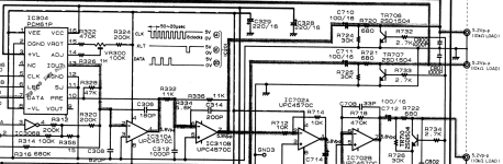
May be easier to sim than to calculate. Because of the feedback around IC310B, C312 will probably cause some frequency peaking effect, at least if not for C314. Together they may interact to change the frequency contour of the stage at IC310B. To work it out by hand, maybe assume IC310A is an ideal voltage source, then write and solve the loop equations for the stage around IC310B. Once you get the transfer function then what C312 is doing should become more clear.
You could also use the feedback equation where the B is the proportion of the output that is fed back into the input: https://www.tutorialspoint.com/amplifiers/amplifiers_feedback.htm#:~:text=the gain of the amplifier is the ratio of output,Vo of the amplifier.&text=The quantity β = Vf,feedback ratio or feedback fraction. IIRC it is assumed B is unilateral, but that's probably a reasonable approximation in this case.
Also: https://www.allaboutcircuits.com/textbook/semiconductors/chpt-8/divided-feedback/
Last edited:

Thank you Markw4 and sorry for the delay, was a bit busy with my job. I'd say I have an idea of what the op-amps do, but I keep having doubts on those ceramic caps which are for sure acting as small microphones for the signal. You're right, easier to simulate, or even better to measure with a scope but I have no scope (it's time to buy one, along with a decent DMM).
BTW I snipped the caps on the output RCAs and on the headphone output (together with muting transistors) and I got only benefits. Perhaps I could try and listen...
BTW I snipped the caps on the output RCAs and on the headphone output (together with muting transistors) and I got only benefits. Perhaps I could try and listen...
Ceramic caps shouldn't be a problem if they are C0G/NPO types rated for at least 50v or 100v. Its the other kinds of ceramic caps that are not good to have in the audio path.
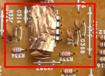
If you can please ignore my crude shielding attempt, those four in the red box are the caps around IC310. They seem to me bog standard, from the service manual they're 50V rated. I assume they are there to filter out the noise from the output current of the dac chip. Do you think is it better go for C0G/NPO or for film caps in that position?
Attachments
Not all film caps are better than C0G/NPO ceramic. Polyester film caps are rather nonlinear. Polypropylene or polystyrene film caps are the best, particularly if made with 'foil and film' construction. Metalized film is not quite as good in some ways. That said, throwing expensive caps at your CD player probably would be overkill.
Regarding the function of the caps we have been talking about (e.g C312), I don't think it is to act as a LP filter since the caps are in a feedback loop. What they do is reduce feedback at higher frequencies. However, there is already a feedback cap that makes the opamp into a LP filter (e.g. C314). Therefore the caps you have been asking about help to shape the contour of overall LP filter. If you want to dive into the math and theory behind why that is, we can do that. Main point is I would not assume that each individual cap makes another LP filter for the dac output. Its a little more complicated than that.
Regarding the function of the caps we have been talking about (e.g C312), I don't think it is to act as a LP filter since the caps are in a feedback loop. What they do is reduce feedback at higher frequencies. However, there is already a feedback cap that makes the opamp into a LP filter (e.g. C314). Therefore the caps you have been asking about help to shape the contour of overall LP filter. If you want to dive into the math and theory behind why that is, we can do that. Main point is I would not assume that each individual cap makes another LP filter for the dac output. Its a little more complicated than that.
Last edited:
I should have some FKP lying around. But, at least to my eyes, C308 and C312 are not in the feedback loop (C306 and C314 are). Albeit without any damping resistor, C308 and C312 "shunt" to ground some high frequencies. Am I completely wrong?
C312 does shunt some HF to ground, but it is HF coming from its feedback loop. It sort of forms a voltage divider with C314. Actually though, R336 is in parallel with C314.
Also, R332 is effectively in parallel with C312. That's because the other end of R332 is connected to an approximate voltage source. By superposition we treat that the same as a ground for the purposes of calculating IC310B feedback.
So what we have as a feedback network for IC310B is effectively a voltage divider with the upper leg Z = R336 || C314, and the bottom leg of the voltage divider Z as = R332 || C312. To solve that for a given frequency we can use complex algebra, or to solve it for all frequencies and get the poles and zeros of the transfer function we would use Laplace transforms. A lot of people seem to find sims more to their liking.
Ahah, I remember the ol' good times of my Laplace (and Fourier) transforms at the University. Thanks for your time for reminding explaining for me. I quickly tried some on-line simulators, but so far I didn't find something handy enough (at least for me). Now I'm interested and will gladly grab paper and pencil (yes, plane old school) to do some small math in "s" space. Thank you again Mark
- Home
- Source & Line
- Digital Source
- (Denon DCD-980) PCM61p RFC on iv and lpf?