Hi there
I have settled for building the BASIC ICG circuit from Decibel Dungeon.
I am now at the ordering parts stage
Ordered 6 LM3875 chips which should be here by next Tuesday.
And this is the problem I have right now, makeing sure I get the right parts.
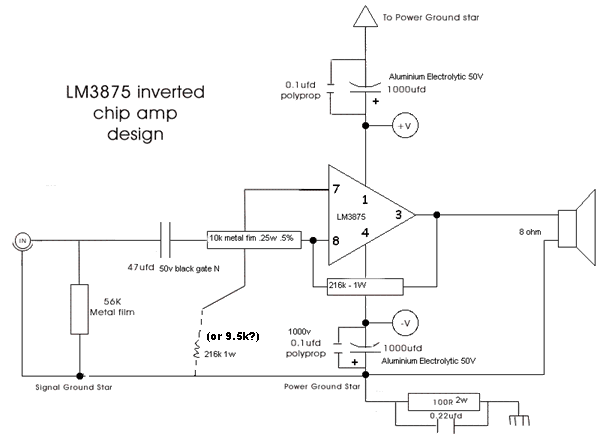
Would someone please look over the circuit diagram and check or suggest components.
I need to be sure of;
which are critical components (which need to be best quality)
Minimum voltage rateing
Minimum wattage rateing
capasitor types (i.e. electrolitic / ceramic), preffered brands?
There is a component I'm not sure of
0.22ufd cap at bottom right, not sure which voltage /type to use
Is there a way to replace the 56k resistor with a suitable potentiometer?
P.S. I will have more questions, no doubt...
Especialy when it comes to the powersupply part, as this version is a little diffirent from other GC PSU's I have seen...
I just have to think my questions through properly, and then translate it to english...
Attachments
Hi Nordic
I think the cap is this one:
http://www.maplin.co.uk/Module.aspx?ModuleNo=361&TabID=1&source=23&doy=13m9
so its probably rated at 240v- maybe someone else could double-check
The BG cap should be 4.7uf
atb
evo
I think the cap is this one:
http://www.maplin.co.uk/Module.aspx?ModuleNo=361&TabID=1&source=23&doy=13m9
so its probably rated at 240v- maybe someone else could double-check
The BG cap should be 4.7uf
atb
evo
I saw when going through the GC site they reference it to BX72X... is the X part important, because I see Maplin only show the BX72K one...?
Why do you suggest 4.7ufd in stead of th 47ufd in the original diagram?
Why do you suggest 4.7ufd in stead of th 47ufd in the original diagram?
Hi Nordic,
I think they're typo's (mistakes) in his spreadsheet he lists the BG as a 4.7 and i think he's put X instead of K
http://myweb.tiscali.co.uk/nuukspot/decdun/gainclonesl.html
HTH
evo
( i would wait for someone else to confirm this though) 😉
I think they're typo's (mistakes) in his spreadsheet he lists the BG as a 4.7 and i think he's put X instead of K
http://myweb.tiscali.co.uk/nuukspot/decdun/gainclonesl.html
HTH
evo
( i would wait for someone else to confirm this though) 😉
On the other hand isn't it supposed to balance each other out?
i.e. the 47ufd cap + 10k resistor to pin 8 VS 56K resistor between input and ground.
i.e. the 47ufd cap + 10k resistor to pin 8 VS 56K resistor between input and ground.
DOh!!!
OK found an article on the CyClone
http://www.platenspeler.com/diy/amps/uk_cyclone_1.html
Based on this the 4.7uf value is probably the correct one...
but the R3 = (R1*R2)/(R1+R2) rule trows me a bit, as in stead of the 9.5K the formula would suggest, the IGC uses a 216K load (the line that looks like this - - - - ) would the 9.5k resistor be better suited? 😕
OK found an article on the CyClone
http://www.platenspeler.com/diy/amps/uk_cyclone_1.html
An externally hosted image should be here but it was not working when we last tested it.
The inverted configuration is said to be even better sounding, so therefore I'm very much interested in hearing an inverted clone. If we suppose a gain which is equal to the gain of my GeenKloon 20x (26dB) then the following formulas describe the amp.
Gain = (R2/R1) = 200,000/10,000=20 times, which equals 26dB.
The best value for R3 can be determined using the following formula:
R3 = (R1*R2)/(R1+R2) which equals 9.5kOhm.
In order to preserve low frequencies the value for capacitor C1 must be chosen sufficiently high. 2.2uF may be on the low side, 4.7uF is used more often.
Based on this the 4.7uf value is probably the correct one...
but the R3 = (R1*R2)/(R1+R2) rule trows me a bit, as in stead of the 9.5K the formula would suggest, the IGC uses a 216K load (the line that looks like this - - - - ) would the 9.5k resistor be better suited? 😕

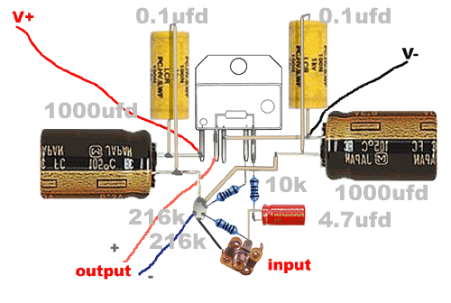
Provisional layout
Bump questions regarding potentiometer, and also the resistor from pin 7's value....
Please excuse repeated posts, but I'm using this thread as an ongoing journal for my benefit and other noobs' too. So I will occasionally just post stuff here to remember as I go along.
What's that additional line from the input to the star ground (more or less parallel to the input grounding R?
No Zobel?
No separation of signal and power ground?
Mick
No Zobel?
No separation of signal and power ground?
Mick
Hi Mick are you talking about the black line to the RCA socket?
that connects to the negative pole, I suppose I could just do the resitor directly between the two poles as oposed to the the ground star...
Would it make a difirence haveing only 1 ground?
Aren't the seperate grounds connected anyway?
i.e.

Circuit for reference

that connects to the negative pole, I suppose I could just do the resitor directly between the two poles as oposed to the the ground star...
Would it make a difirence haveing only 1 ground?
Aren't the seperate grounds connected anyway?
i.e.

Circuit for reference

It is common practice to separate signal and power ground and as far as I know it is also recommended by National in one or the other data sheet. Have, for example, a look at the LM4780 data sheet and the reference board described in it. Also, have a look at decibel dungeon concering grounding practice, the separation is discussed there.
I understand the black line now. Yes, you could to the resistor directly between the poles of the RCA socket and that point would be your signal star then. Look at Decdun.....
Mick
I understand the black line now. Yes, you could to the resistor directly between the poles of the RCA socket and that point would be your signal star then. Look at Decdun.....
Mick
Back to the power and signal stars... please help me visualise...
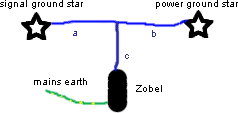
How does the seperate stars connect to the mains earth, is it like I have in this picture?

Also read about people using difirent guages of wire for this, what goes where?
How does the seperate stars connect to the mains earth, is it like I have in this picture?

Also read about people using difirent guages of wire for this, what goes where?
Hahaha, well that was exactly the thread that confused me... maybe I should read it slower....
The case is not going to be a metal construction so there will be no chasis grounding....
As for the other question, I received an answer from Nick Whetstone at DD...
It seems he reverted to removing the resitor from pin 7 and replacing it with plain wire... think I might be on to something with the 9.5k resistor, which is what I will try.
Yes, the feedback value on that basic circuit is 216K (which I got from 2 432K's in parallel). It's not too critical that value and 20K -27K is fine.
It was suggested that the resistor from pin 7 to ground could be the same
value as the feedback resistor to reduce DC offset to zero. This does work
but I don't think that it sounds as good. After much experimenting, I am
happy to have some DC offset (ie under 100mV) and just have a piece of wire
from pin 7 to ground because that sounds best to my ears.
Thanks for pointing out the error on that diagram.
Cheers,
Nick
Well I started this thread on the 14th of last month, only today did I receive my transformer, the size is plain phsyco, think I need to attach wheels... Quality is awesome, (it was custom wound for me) even has a fresh coat of black paint on the body. Thinking of makeing a transformer cover for the side and dropping it in through the PSU lid like a vale amp's trannies...
Anyhow, the simple PSU is done in veroboard, delivering 33.6V on each rail, using the Rod Elliot PSU. http://sound.westhost.com/project04.htm .
I laid out the veroboard so that I can also try Carlos' snubber circuit as soon as I have the appropriate resistors, Only have 1R, 10k and 100K resistors in high wattage package tight now...
Right now, I only have 4 x 10 000ufd Capacitors on the PSU.
But heck I am over the moon, I even went to fetch the torch in case the lights go off when I pluged the Supply into the wall.
All went well😎

Working !!!! Working... OMW... didn't think it would be this good
My Sansui amp now sounds like poopie. Now to find a proper heatsink, the small one I used ot realy hot afer 10 minutes...
Used my hifi speakers, wow, could keep on turning up the volume, and they just didn't distort like they normal do when given some juice...
My Sansui amp now sounds like poopie. Now to find a proper heatsink, the small one I used ot realy hot afer 10 minutes...
Used my hifi speakers, wow, could keep on turning up the volume, and they just didn't distort like they normal do when given some juice...
Well done!
One of the things that makes diyAudio such a great place to mod is the amount of sheer joy that is evident when people build something they like.
Beats sorting out playground fights anyday!
One of the things that makes diyAudio such a great place to mod is the amount of sheer joy that is evident when people build something they like.
Beats sorting out playground fights anyday!
Thanks, will order some proper PCBs for them, the spiders looks very unsteady... I was so scared powering it on after he first one went poof...
What would the proper rateing be for heatsinks per chip in C/W, and do I just double it to add 2 chips to it?
What would the proper rateing be for heatsinks per chip in C/W, and do I just double it to add 2 chips to it?
Why use a PCB if PTP is okay? hehehe that's just me.
In post#7 you use decibeldungeon schematic, only differ in the input resistor, but seems that your input cap is only 4.7uF not 47uF (47uF BGN is bigger, BGNX is smaller). Smaller cap will have better sound IMO, but how about the low frequency cut-off?
In post#7 you use decibeldungeon schematic, only differ in the input resistor, but seems that your input cap is only 4.7uF not 47uF (47uF BGN is bigger, BGNX is smaller). Smaller cap will have better sound IMO, but how about the low frequency cut-off?
The 47ufd in the scematic is an error, the parts list confirms it as 4.7ufd....
Noticed something last night, the 2 channels works fine when using either of them with our satelite dish decoder, but when I plug both channels in it makes a loud ringing noise... the noise stops the second I unplug either of the inputs....
How do I go about fixing that....
Also I resoldered the circuit using a picture I made of what should go where while planning, and its now much more solid (I did cheat by adding a single strip of veroboard for pin 8 to connect the input resistor and cap on)...
While both channel produces good bass, the 2,2 just has a bit too much treble for my liking, (got to get used to sound this clear again first)
- Status
- Not open for further replies.
- Home
- Amplifiers
- Chip Amps
- Decibel Dungeon GC w/LM3875
