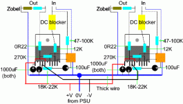
NuuK. I have put together an LM3886 as per your circuit (the only change being OR22, for which I used a 1R WW res as it was all I had.
I don't appear to have any output (yet seem to read -5v DC offset ?)
I have put together a power supply to run it with. the DC +V and
-V is 47.3V.
I am getting the following readings :-
Pin 1 - 3 37.3
Pin 1 - 4 40.3
Pin 1 - 7 32.2
Pin 1 - 8 34.6
Pin 1 - 9 36.3
Pin 1 - 10 32.2
By the way I am getting a strange reading from the PS, +V and OV = 32.5, -V and OV = 15V
Any help you can give would be appreciated.
Don't know if photos will help
http://i73.photobucket.com/albums/i239/saxonsex/chip2.jpg
http://i73.photobucket.com/albums/i239/saxonsex/chip.jpg
http://i73.photobucket.com/albums/i239/saxonsex/chip2.jpg
http://i73.photobucket.com/albums/i239/saxonsex/chip.jpg
I believe he is saying his V+ rail is 32.5V and his V- rail is -15V for a total difference of 47.5V. Definitely something odd happening there.
I reckon you have a short somewhere! Disconnect the PSU from the chip and measure it again to make sure it is correct.
Then check for shorts.
The chip isn't insulated from the heatsink is it?
Check for any shorts.
Are you using a muting cap?
Then check for shorts.
The chip isn't insulated from the heatsink is it?
Check for any shorts.
Are you using a muting cap?
Hello Puffin, i can see no V- connection to pin 4..?The neg side of that 1000uf cap connects to 4 as well, with the pos side to ground..
I wondered about that as well, but if the neg rail isn't connected, he should be getting the full rail voltage on the output!
NuuK. Voltage with chip disconnected +v and -v = 60.6, +v and Ov =32.8, -v and Ov = 27.8
With chip connected +v and -v is 47.1, +v and Ov is 32.10 , -v and Ov is -15v
With chip connected +v and -v is 47.1, +v and Ov is 32.10 , -v and Ov is -15v
Audio1st. The neg of the 1000uf is connected to pin 4. There is a resistor between pin 4 & 8 and the neg of the 100uf is connected to pin 8 as well.
NuuK. Voltage with chip disconnected +v and -v = 60.6, +v and Ov =32.8, -v and Ov = 27.8
32.8-27.8 = 5 v which is what you have on your output! 😉 So why isn't your PSU symmetrical? You need to check out the PSU!

Puffin, Is your V- the blue wire with yellow tape.? If so it should connect direct to pin 4.
Desolder from its present location, solder to pin 4 and add a wire from were it was to ground..
Desolder from its present location, solder to pin 4 and add a wire from were it was to ground..
Audio1st. O.K I have done (connecting wire to pin 4) that and I now get a power on/off click through the speaker, but no signal in.
Member
Joined 2003
Well the PSU needs a bit of sorting out...but I have got it working ! Sounds quite good, looks like shite, but......hey first time.
Now need to tidy it up and make another one for stereo. Thanks for all your help.
Now need to tidy it up and make another one for stereo. Thanks for all your help.
So what was the problem?
From The Prophet by Kahlil Gibran
You are the way and the wayfarers.
And when one of you falls down he falls for those behind him, a caution against the stumbling stone.
Ay, and he falls for those ahead of him, who though faster and surer of foot, yet removed not the stumbling stone.
From The Prophet by Kahlil Gibran
- Status
- Not open for further replies.
- Home
- Amplifiers
- Chip Amps
- Decibel Dungeon Gainclone
