Hi everyone,
I have question about fm tuner de-emphasis. I have recently obtained (chieply) fm tuner Luxman T-404. Its european model, but I live here in us. In comparison to other tuners I have (technics 9038, SAE T6, JVC tx300, yamaha tx350 and others) this one has european de-emphasis and sounds too bright. Otherwise I believe its a nice tuner. Look inside is very pleasing, all good chips, high quality construction.
I would like to correct its increasing hights with some simple (preferably passive) shelving filter. I do not want to alter anything inside, just in case I decide to sell it later on european ebay. Can any of you come up with simple filter I can insert on its output before signal selector on the active crossover? (I do not use preamp, just buffered line level crossover)
You need a pole/zero at 75 and 50us
10k in series with tuner to preamp (includes output impedance)
16k in series with 3n3 from amp input to ground assuming 47k I/P
10k in series with tuner to preamp (includes output impedance)
16k in series with 3n3 from amp input to ground assuming 47k I/P
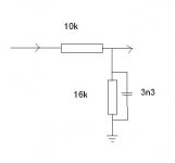
Is this any use ?
American vs European FM (de-emphasis)
the best option is really changing the values within the tuner if at all possible. They shouldn't be to hard to locate with luck.
Remember any "add on" filter you design is already working with what is already there and you will have to ensure the impedances are correctly accounted for.
Here's a typical chip, de emph components R4 and 5 and C11 and 12
http://www.datasheetcatalog.org/datasheet/sanyo/ds_pdf_e/LA3450.pdf
Easy to refit back any changes at a later date.
that's a very good point Mooly, its easier to work on modifying de-emphasis inside rather than working on correnction with impedance mismatch
the stereo decoder inside is Sanyo LA3401, which is pretty common and the datasheet is available
so I might go that way...
thank davidsrsb for input as well...
the stereo decoder inside is Sanyo LA3401, which is pretty common and the datasheet is available
so I might go that way...
thank davidsrsb for input as well...
For the LA3401 it's the caps marked C14 and 15 here.
Adding a 220pf across each would give 73us... pretty close, or you could take them out and replace with 750 pf.
You could always alter the resistors R1 and R2 as well, at the expense of greater output. 150k would give 76us.
You would have to try that one to make sure there was sufficient headroom for the higher output level.
Attachments

done!
it was easy to locate the parts
I ended up soldering it to the caps directly since turning the pcb would be hard
thanks for the help
ed
btw there is clearly a place for the de-emphasis switch and a number of other parts on the board, but its not populated
there is even a place for the noise reduction circuit...but the chip is not there!
ok, I got the lower model
Last edited:
That's good, and it has to be better than adding a christmas tree network on the outputs.
The switch off for FM in the UK is getting nearer... that should be fun, enjoy while you can.
The switch off for FM in the UK is getting nearer... that should be fun, enjoy while you can.
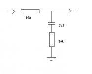
The 3n3 should be in series with 16k, not in parallel as Adason drew
But I think that changing the internal time constant is a much better solution as there are no dependancies on input and output impedances
My Sony STS-361 has the same Sanyo chip and sounds very good
But I think that changing the internal time constant is a much better solution as there are no dependancies on input and output impedances
My Sony STS-361 has the same Sanyo chip and sounds very good
- Status
- Not open for further replies.
- Home
- Source & Line
- Analogue Source
- de-emphasis in fm tuner