What voltage do you mean?
Working voltage?
Mains power voltage?
Schematic or at least a clue to what you are looking at may be useful.
Working voltage?
Mains power voltage?
Schematic or at least a clue to what you are looking at may be useful.
Hi there,
I need to change the main power which is set for 100V to1115V . There is a power power selector Board with the orange jumprers.

I need to change the main power which is set for 100V to1115V . There is a power power selector Board with the orange jumprers.
There is no technical information about DCS, you can only access your mains voltage version from the menu.
If you want to change the input mains voltage, you have to go through an official DCS dealer. Or if you feel able, reverse engineer the circuit and deduce the correct wiring.
If you want to change the input mains voltage, you have to go through an official DCS dealer. Or if you feel able, reverse engineer the circuit and deduce the correct wiring.
dCS does not provide with voltages in the menu and wants 600US for repositioning 2 or or jumpers. Are they not a crooks?

They may not all use the same traffo and wiring. Easy enough to probe the pins in that block though.
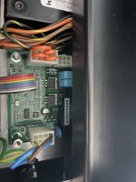
I think the 6 pin socket on the right is connect to the power transformer primary windings and the 10 pin socket on the left is jumpers to configure voltage selection.
I think the 6 pin socket on the right is connected to the power transformer primary winding and the 10 pin socket on the left is the jumper to configure voltage selection.
First, identify the primary winding by its resistance. Then check which pins in the 10-pin socket belong to the 100V tap and the 120V tap. Move the two jumpers connected to the 100V tap to the 120V tap.

Based on the image, the hardest part is identifying which pins belong to the 100V tap, maybe taking a photo of the back of the board will help.
I think the 6 pin socket on the right is connected to the power transformer primary winding and the 10 pin socket on the left is the jumper to configure voltage selection.
First, identify the primary winding by its resistance. Then check which pins in the 10-pin socket belong to the 100V tap and the 120V tap. Move the two jumpers connected to the 100V tap to the 120V tap.
Based on the image, the hardest part is identifying which pins belong to the 100V tap, maybe taking a photo of the back of the board will help.
Last edited:
Hello,
First of all I would like to say THANK YOU very much to try to help me.
And you are right, The six pins sockets are supplying voltage to the transformer's primaries. I uploaded some pictures.
First of all I would like to say THANK YOU very much to try to help me.
And you are right, The six pins sockets are supplying voltage to the transformer's primaries. I uploaded some pictures.
Attachments
![IMG_3797[1].JPG](/community/data/attachments/1259/1259637-b64beb637d8e2afadbf77f6b3e4952d5.jpg?hash=tkvrY32OKv)
![IMG_3798[1].JPG](/community/data/attachments/1259/1259638-4718ef26f7506a90e0d04e8c7bcd7a43.jpg?hash=RxjvJvdQap)
![IMG_3799[1].JPG](/community/data/attachments/1259/1259639-801cd5e2b2b953bba49f4622bc4fae08.jpg?hash=gBzV4rK5U7)
![IMG_3800[1].JPG](/community/data/attachments/1259/1259640-4beab0a682f8deae822ae5ce2652a8c0.jpg?hash=S-qwpoL43q)
![IMG_3804[1].JPG](/community/data/attachments/1259/1259654-c4e740265849463bc498ed7ef2fc46e1.jpg?hash=xOdAJlhJRj)
![IMG_3806[1].JPG](/community/data/attachments/1259/1259686-b6d9f200a09f4c8a0e1f95bce6d6f40a.jpg?hash=ttnyAKCfTI)
This is what I based on the provided photo and logic drew out the 120V jumper settings. Please confirm pin 7 and 9 are connect to mains L and N.
However, there's one missing puzzle, I don't know where is pin 1 going to and I guess 4 is connected to pin 7? Maybe you can trace the circuit, or someone more knowledgeable see this and offer some advise.

Sorry, I can't provide a definite answer at this stage on how to convert this to 120V.
However, there's one missing puzzle, I don't know where is pin 1 going to and I guess 4 is connected to pin 7? Maybe you can trace the circuit, or someone more knowledgeable see this and offer some advise.
Sorry, I can't provide a definite answer at this stage on how to convert this to 120V.
- Home
- Source & Line
- Digital Source
- dCS Verdi Transport. How to change the voltage