I'm not quite understanding the behaviour of the DC heater supply I just put together, and would welcome some explanation.
Circuit is a standard regulator one, from the usual data.
With a VS-KBPC602, Bridge Rectifier, 6A 200V I get:
Voltage into reg = 5.6v.
Voltage out of reg into 2x4V tubes @ 1850mA = 3.4v
With 4 Schottky diodes rated 5A, 40v I get:
Voltage into reg = 6v.
Voltage out of reg into 2x4V tubes @ 1850mA = 3.1v
Voltage offload from the LM1084 reg is 3.9v.
So why am I not getting 3.9v out? And why is the Schottky version only giving 3.1v out despite 6v in? The LM1084 is a LDO reg isn't it?
So to get 3.9v out do I just change the 470 ohm resistor until the voltage under load is correct?
The transformer is 6v, 20VA and doesn't seem to be getting hot, and nether is the reg hot.
Attachments
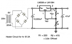
Vout = 1.25 * (1 + R2/R1)
So I make R2 = 4.04 * R1 for 6.3V so 888R.
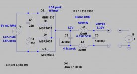
I find you can loss a lot in the transformer and diodes. There's also a lot of ripple on the supply cap pushing the reg out of regulation. So for 3A @ 6.3V I ended up with much bigger transformer and 22000uF @ 10V cap. As for diode I used 80SQ045NG.
So I make R2 = 4.04 * R1 for 6.3V so 888R.
I find you can loss a lot in the transformer and diodes. There's also a lot of ripple on the supply cap pushing the reg out of regulation. So for 3A @ 6.3V I ended up with much bigger transformer and 22000uF @ 10V cap. As for diode I used 80SQ045NG.
Last edited:
Vout = 1.25 * (1 + R2/R1)
So I make R2 = 4.04 * R1 for 6.3V so 888R.
I find you can loss a lot in the transformer and diodes. There's also a lot of ripple on the supply cap pushing the reg out of regulation. So for 3A @ 6.3V I ended up with much bigger transformer and 22000uF @ 10V cap.
Thanks! This is for 4v tubes, not 6.3v tubes. Assuming 120 ohm for R1, then R2 should in theory be 270 ohms, but maybe needs to be higher.
I'm reluctant to go up to a 9v transformer, though that should solve the issues. If I can get it working with a LM1084 and 6v transformer that would be more economical. It's only for a heater supply so not uber critical.
You should have no issue try C = 2x10000uF. What's the AC voltage on your transformer secondary when loaded?
You should have no issue try C = 2x10000uF. What's the AC voltage on your transformer secondary when loaded?
Vac is 6.25V on secondary of transformer when loaded. There's 300mV AC on the 10,000uF capacitor.
.
Last edited:
Your bridge rectifier is losing quite a bit of voltage. I'd try SB520 diodes in DO201 You should be able to get there with a LM350
If memory serves me right, LT1083 has a dropout voltage of 1.3V @ 3A now the LM1083 is slightly worse.
It could be that your R1 and R2 are not connected near the load, and wiring/contact resistance is causing this 600mV shift in loaded/unloaded voltage.
Another possibility is oscillation, these PNP pass element LDO regulators dont nearly have the same stability as something like a LM317 which is much more stable, i saw you drew in a 47uF capacitor? When the recommended value is 150uF aluminium electrolytic.
Maybe this is because of cold filaments , the regulator can't recover from overcurrent protection ... it should be tested on a dummy load .
Your bridge rectifier is losing quite a bit of voltage. I'd try SB520 diodes in DO201 You should be able to get there with a LM350. If memory serves me right, LT1083 has a dropout voltage of 1.3V @ 3A now the LM1083 is slightly worse. It could be that your R1 and R2 are not connected near the load, and wiring/contact resistance is causing this 600mV shift in loaded/unloaded voltage. Another possibility is oscillation, these PNP pass element LDO regulators dont nearly have the same stability as something like a LM317 which is much more stable, i saw you drew in a 47uF capacitor? When the recommended value is 150uF aluminium electrolytic.
OK - I can substitute a 150uF and I'll order some SB520 diodes.
I have the tubes connected via a clip lead. There will indeed be some distance from the voltage reg, like 200mm, to the tube. So I should use thicker wire.
I can add 10,000uF to the reservoir cap to make it 20,000uF. Maybe that would help?
I could use a LM350 - what's better about this than the LM1084? It's rated 3A. Good point about cold filaments - they may be drawing 3A on switch-on. Sounds safer to have a 5A reg.
I expected this to be a simple circuit, but it's far from that to do it properly!
.
Last edited:
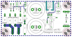

OK - progress here. I added 10,000uF to the reservoir cap to make it 20,000uF. I also used a 220uF electrolytic on the output. Voltage at the tubes went up from 3.1v to 3.3v so some gain.
But the loss is in the clip leads. The voltage at the reg is 3.9v so it's working properly. I'll have to put the supply in circuit and measure the voltage at the tubes, using thicker wire for the connection. Then increase the value of R2 until the voltage at the tubes is close to 4v.
Does that sound like a solution? Thanks for the help.
Hi Andy,
The thing that has been missed is the transformer, if it is 6V 20VA. The rated rms current at full load and reasonable crest factors is only a little over 3A.
If you want to supply 2A DC, from rectifying this winding into large caps, the rms current drawn will be nearer to 3.8 - 4A. This is likely a factor in why you saw such a loss of voltage.
With 10-20000µF caps, the crest factor is anything but reasonable, and so 60-100% de-rating is advisable. A 6V winding should really be rated for 50VA, rather than 20VA for such a design.
With an uprated transformer, the 5A 40V schottky diodes should be fine, and you should get nearer to 7V DC on load.
The capacitors should be 16V for preference, or they may sweat with the ripple current. 16V types have lower losses than 6.3 or 10V, in general.
Yep that's what I found too - had to use a much larger transformer because of the DC winding resistance. I ended up with 50VA after finding the 30VA was causing the the reg to drop out. As for caps I went for 10V long life/high temperature types - low ESR is better.
I have some 30VA and 50VA transformers. That will be an improvement. I was going by how cool the transformer was running, and just happened to have a 20VA on the shelf. In future the transformer will be bigger.
I am indeed using 16v capacitors.
Thanks for the help everyone - a simple circuit but one which requires some care to do it properly.
I am indeed using 16v capacitors.
Thanks for the help everyone - a simple circuit but one which requires some care to do it properly.
- Home
- Amplifiers
- Tubes / Valves
- DC voltage regs for heater supply.