Hi every one!
I need some help with my investigate of my amplifier. Nothing on this amp has been or is burnt. Still i get around 1.2V DC on output to speaker after rele is on. I have changed all electrolytic in scematic without change in level of DC. Any ideas what i can check next?
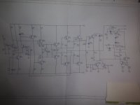
I have checked all transistors with diode testing and it measures ok, No shorts or Open circuits. Not the best picture but it shows the output stage.
I need some help with my investigate of my amplifier. Nothing on this amp has been or is burnt. Still i get around 1.2V DC on output to speaker after rele is on. I have changed all electrolytic in scematic without change in level of DC. Any ideas what i can check next?
I have checked all transistors with diode testing and it measures ok, No shorts or Open circuits. Not the best picture but it shows the output stage.
Attachments
Would you measure the following points with respect to ground:
Base Q400
Base Q401
Amp Output
Junction C408 and R407
Please report voltages as signed numbers, and best resolution your meter offers.
BTW, does C408 appear to be installed with the correct polarity?
Thanks.
Base Q400
Base Q401
Amp Output
Junction C408 and R407
Please report voltages as signed numbers, and best resolution your meter offers.
BTW, does C408 appear to be installed with the correct polarity?
Thanks.

I'll add to check the voltage across ZD400 is correct (5.6 volts, if low suspect the 47k feeding it)
Check R431 is intact which is the 5.1 ohm in the Zobel network on the output.
It is possible it could be instability causing an apparent DC shift at the output due to an asymmetric HF oscillation. Ideally a scope check would be needed.
The other question I've started asking 🙂 Does it have an unknown history and has it been worked on before by persons unknown?
Hi.
Result of my measure is:
Voltage accross ZD400 was 5.52V.
Base on Q400 = 106mVDC
Base on Q400 =1.016VDC
I see no deviation in resistorvalues mentioned.
I Will check futher on this SG4 feeding Q400 base. It is coming from an opamp in preamp section.
Result of my measure is:
Voltage accross ZD400 was 5.52V.
Base on Q400 = 106mVDC
Base on Q400 =1.016VDC
I see no deviation in resistorvalues mentioned.
I Will check futher on this SG4 feeding Q400 base. It is coming from an opamp in preamp section.
That's fine.Voltage accross ZD400 was 5.52V.
You mean Q401. That voltage is high but expected with the high offset.Base on Q400 =1.016VDC
Was R431 OK?
Just pull C401 out to isolate the earlier stages.I Will check futher on this SG4 feeding Q400 base. It is coming from an opamp in preamp section.
Yes, sorry it is Q401. This has 1.016V at base. R431 is spot on 5.1R.
But is level at Q401 to high?
But is level at Q401 to high?
Yes it is too high but that isn't necessarily the actual issue, it is an effect of the high offset.
Having 0.106 volts on Q400 base and over a volt on Q401 base would suggest the offset at the output should be massive (like stuck to a rail) because the input stage is so out of balance... but its not and that is why I suspected possible instability.
It is definitely worth isolating C401 just to make sure no unwanted AC of any sort is getting into the amp via its input.
Does it work (sound) OK apart from this offset problem?
Forgot to mention that i have disconnected speaker due to this DC.
Speaker is luckly, still intact anyway.
Speaker is luckly, still intact anyway.
What should happen is that Q401 base being high should turn on Q401 more and pull base current through Q402 turning that on more. In turn that develops more voltage across R422 and turns on Q411 more which in turn then gets the PNP driver Q412 and the lower PNP output transistors to conduct more pulling the output voltage down. That should bring the circuit into a state of balance with a low offset.
Fair enough. I asked because if the sound was OK then it means the lower part of the output stage is basically OK and that is what needs to be working to pull this offset back down.
(An offset of a couple of volts will not damage a speaker as it can not allow enough current to be drawn but of course if it were intermittent and suddenly jumped higher than that would be bad news)
Try isolating the input first. If that's no good then I'm going to suggest you do some careful (because one slip and it all goes pop) voltage checks by measuring across the base emitter junctions of all the transistors apart from the outputs. That means meter leads on the actual base and emitter of each. All should be in the 0.65 volt region, you are looking for bigger variation such as one with say 0.9 across it.
The base will be the most positive for all the NPN's and the most negative for all the PNP's.
But be careful. Perhaps locate components that go to these points and measure from those is it is safer.
I'll look in tomorrow and hopefully BSST will have some ideas too 🙂
Forgot to mention that i have disconnected speaker due to this DC.
Speaker is luckly, still intact anyway.
Fair enough. I asked because if the sound was OK then it means the lower part of the output stage is basically OK and that is what needs to be working to pull this offset back down.
(An offset of a couple of volts will not damage a speaker as it can not allow enough current to be drawn but of course if it were intermittent and suddenly jumped higher than that would be bad news)
Try isolating the input first. If that's no good then I'm going to suggest you do some careful (because one slip and it all goes pop) voltage checks by measuring across the base emitter junctions of all the transistors apart from the outputs. That means meter leads on the actual base and emitter of each. All should be in the 0.65 volt region, you are looking for bigger variation such as one with say 0.9 across it.
The base will be the most positive for all the NPN's and the most negative for all the PNP's.
But be careful. Perhaps locate components that go to these points and measure from those is it is safer.
I'll look in tomorrow and hopefully BSST will have some ideas too 🙂
I'd check R400/401 now that you know Q400/401 is out of balance. As mooly says Q401 should be steering all the current down its collector. So R401 collector connection should be much lower voltage. I had a problem on an amp where the beta degraded on the input pair. I looked up your pair and beta's are not spec'd high like mine were, so I am doubtful it is that in your case. Still though, given the offset at the input pair, should be easy to trace forward to see where the DC voltage correction in the feedback that should be happening is not.
As has been explained, given the current failed state, the feedback should push the tail current through Q401, and should eventually drive the amp output toward 0V, but somewhere this process is failing. Now that we have data at the input pair, I suggest measuring several points to get a sense of how the amp is responding/not responding:
Please measure the following 6 points with respect to the +48V rail:
BCE of Q402
BCE of Q403
Please measure with respect to the -48V rail:
BCE of Q411
And collector to emitter voltage across Q404
Thanks.
Please measure the following 6 points with respect to the +48V rail:
BCE of Q402
BCE of Q403
Please measure with respect to the -48V rail:
BCE of Q411
And collector to emitter voltage across Q404
Thanks.
Hi.
Following your advice i found these measurements:
E on Q403 = 0.09V
B on Q403 =0.74V
C on Q403 =48.99V
E on Q402 = 0.76V
B on Q402 = 1,40V
C on Q402 = 96.78V
E on Q411 = 0.09V
B on Q411 = 0.74V
C on Q411 = 46.8V
EC on Q404 =1.84V
Following your advice i found these measurements:
E on Q403 = 0.09V
B on Q403 =0.74V
C on Q403 =48.99V
E on Q402 = 0.76V
B on Q402 = 1,40V
C on Q402 = 96.78V
E on Q411 = 0.09V
B on Q411 = 0.74V
C on Q411 = 46.8V
EC on Q404 =1.84V
I'm liking Mooly's suspicion of oscillation. Is a scope available? Perhaps C410 in the Zobel has opened. Also check continuity of C410 and R431 leads: i.e. measure each of the four components leads to its respective connection so that open traces or via can be discovered. Let me know if my suggested test method isn't clear.
My suspicion of oscillation is raised because the severe offset in the input pair should tip the tail current toward heavy condition in Q401, yet the amp output is biased near 0V. This shouldn't be the case given the big offset error.
My suspicion of oscillation is raised because the severe offset in the input pair should tip the tail current toward heavy condition in Q401, yet the amp output is biased near 0V. This shouldn't be the case given the big offset error.
Hi Again,
Sorry, it took so Long to get back.
Thank You all for helping me.
I finally got rid of DC from output.
Guess what, i replaced Q400 and Q401.
Now it shows 0VDC after rele clicks on at speaker and also without any sparking sound i speaker.
Thanks again to all at DIYAudio.
It is a nice place to be member of.
Regards,
Bjorn
Curious, did you measure the beta of the old Q400/401? In my case beta was down to about 25% of spec when I replaced my front end pair. And congrats, always nice to get an old amp working again.
- Home
- Amplifiers
- Solid State
- DC on output (Active speaker)