As @Mark Johnson suggested I’m opening a new thread for this board.
Here is a link to my original post:
Post#142
After I published my board in the original AmyAlice thread, I made a couple of small change to the board.
1.- spaced the two inductor as suggested by @jackinnj
2.- increased the solderpad dimension for the inductor to be easier to solder.
Components and circuit are exactly the same used on the original AmyAlice project.
Edit 09/23/24
Added BOM for board v 1.1 and v 1.5
Added Gerber for board v 1.5 (see post #10)
Here is a link to my original post:
Post#142
On 2024-07-14 I wrote:
"First of all thank to @Mark Johnson for this very useful project. I started using it from very beginning when Mark published it and I’m very satisfied.
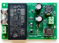
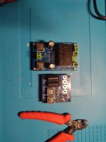
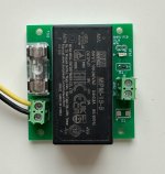
I’ve also used it in some very low power demanding device where I normally use some small encapsulated SMPS. In the beginning I just hooked up the SMPS to Mark’s board, but then I decided to make a dedicated board to avoid having flying wires and to add a fuse.
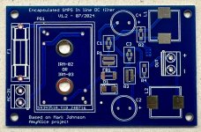
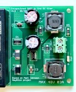
I made this board that can accomodate a Meanwell IRM-02 (2Watt) or IRM-03 (3Watt) with various output voltages.
Schematic and components are exactly the same as Mark’s AmyAlice board.
I don’t want to hijack Mark’s thread and I don’t think that this board deserve a dedicated thread, so if one want to make this board just DM me and I’ll send the Gerber files. I still have some boards available that can give away for mail cost only.
Or, under Mark permission, I can post here the Gerber files."
After I published my board in the original AmyAlice thread, I made a couple of small change to the board.
1.- spaced the two inductor as suggested by @jackinnj
2.- increased the solderpad dimension for the inductor to be easier to solder.
Components and circuit are exactly the same used on the original AmyAlice project.
Edit 09/23/24
Added BOM for board v 1.1 and v 1.5
Added Gerber for board v 1.5 (see post #10)
Attachments
-
 IMG_1696.jpg437.8 KB · Views: 489
 -
 IMG_1698.jpg379.6 KB · Views: 322
 -
Gerber file_Low power SMPS Filter board v1.2.zip87 KB · Views: 86
-
 bare board V 1.5.jpg343.7 KB · Views: 199
 -
 board v1.5.jpg508.6 KB · Views: 287
 -
BOM for Encapsulated SMPS PCB with Mark Johnson AmyAlice filter 1.0.pdf32.6 KB · Views: 79
-
Gerber for SMPS FIlter Amyalice v1.5.zip117.3 KB · Views: 59
-
 SMPS w:AmyAlice.jpg64.2 KB · Views: 307
Last edited:

Got inspiration from the excellent idea by mvaldes to include the SMPS itself. Got the files from mvaldes and imported them in KiCAD which went not exactly fine so I made a new drawing. This is a variation for IRM-05 so 1A as many DACs like some current now and then. Also more clearance as I included plated through mounting holes. I will first have some made and test them.
Yes linear PSU builder but one should keep an open mind.
Yes linear PSU builder but one should keep an open mind.
Attachments

Last edited:
The previous one won't be made as just looking at my sources and DIY linear PSU stuff it was clear that for honest comparison more current is needed. So the IRM-02 (2 watt) and IRM-03 (3 Watt) already included in the original and tested mvaldes design were removed and the design was adapted to IRM-05 (1A), IRM-15 (3A) and the 4A IRM-20 (only because it shares the same footprint). Although 50 mil PCB tracks are limited to 2.6A continuously and the filter is limited to 3A max. it may be nice to have some reserve for peak/power on currents. Of course one can have wide traces and/or double copper but let's keep it affordable for testing first.
Please note that having abundance of power does not imply that one should/must use all that power.
Please note that having abundance of power does not imply that one should/must use all that power.
Attachments
Last edited:
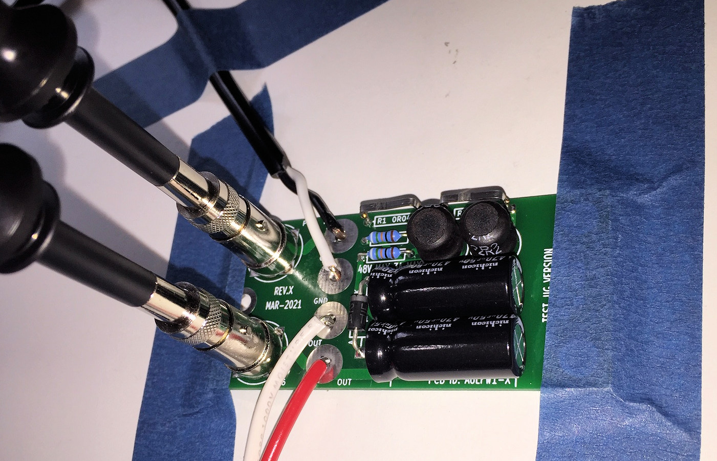
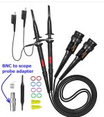
I found it useful to include super-low-inductance grounding for the oscilloscope probes, when measuring the diyAudio Store SMPS filter (thru hole board): {post #515} In my case, BNC RF connectors on the PCB, followed by BNC adapters on the scope probes, worked quite well. Hope this helps.
_

_
Attachments
Difficult when using PCB screw connectors. My test version also lacks a ground plane which I meanwhile added. We’ll see, it is just for testing.
Very nice build. 👍Fun project, actually found this board easier to solder then the original AMY/ALICE.
@Mark Johnson thank you very much for this. I missed that post. I'll for sure make a pcb with these BNC connector.I found it useful to include super-low-inductance grounding for the oscilloscope probes, when measuring the diyAudio Store SMPS filter (thru hole board): {post #515} In my case, BNC RF connectors on the PCB, followed by BNC adapters on the scope probes, worked quite well. Hope this helps.
_
I like to deep test all the stuff I make also when not necessary at all 😃
testing help to understand and to learn a lot.
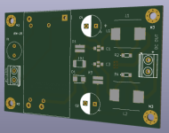
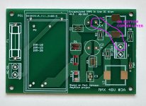
Since there has been some request for a more powerful version and after talking with Jean Paul, I made this new board that can mount some more beefy Meanwell encapsulated SMPS.
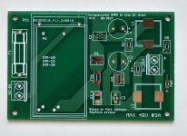
Board dimensions are 87x57mm and there are footprint for three different size that can provide 3A at various voltage:
IRM/MPM-10
IRM/MPM-15
And IRM/MPM-20
Previous board have smaller traces, perfectly dimensioned for small power requirement, while in this version I used polygons instead of normal traces so to have the largest amount of copper in order not only to handle more power, but also to reduce parasitic inductance and high frequency signal ringing. (This is just theory). There are no “follow me” vias between top and bottom layer and of course a large ground plane.
I’ve also added a LED and mounting holes follows the 10x10 grid of Modushop/DIYAudio chassis.
I’m testing this with a RPI streamer since a couple of days, and will soon add the files to first post.
Michele
Attachments

Hi, my parts will arrive monday but as I was operated last Thursday it may take a few weeks to assemble/encase stuff. I made it an MPM-20-5 as it has 50 mV less noise and ripple compared to the IRM version that has a whopping 200 mVp-p max. ripple/noise. As a linear PSU fanatic used to expressing in tens of microvolts of ripple/noise I still think the Meanwell IRM and MPM series have a lot of ripple and would not be usable without the added filter. Probably usable for devices that have internal linear regulators to 3.3V and lower.
The V1.5 board sure looks good. Wait for my V1.6 😀 At second sight it seems you have used one of the coils in the negative side of things.
The V1.5 board sure looks good. Wait for my V1.6 😀 At second sight it seems you have used one of the coils in the negative side of things.
Last edited:
I don't know whether the PCB shown in post #10 will be an excellent filter or not. But I do know that it is a different circuit design than AmyAlice. If you make a post containing both schematics, #10 and also AmyAlice, the differences will be plain to see.
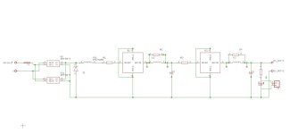
The signal flow of AmyAlice is: Ferrite --> 0R1 --> feedthru --> inductor --> electrolytic --> 0R1 --> feedthru --> inductor --> electrolytic --> output
The signal flow of #10 is: Ferrite --> 0R1 --> feedthru --> electrolytic --> inductor --> electrolytic --> 0R1 --> feedthru --> inductor --> output
Using "F" for ferrite, "R" for 0R1, "T" for feedthru, "C" for electrolytic, and "L" for inductor:
FRTLCRTLC is AmyAlice
FRTCLCRTL is Post #10
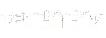

Please have a better look at schematic. Do not rely on what you can "suppose" looking at a PCB...At second sight it seems you have used one of the coils in the negative side of things.
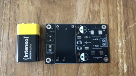
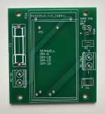
Thanks for the explanation!! Your bare board photo makes the situation extremely clear. Sorry I misunderstood.Hi Mark,
schematic is exactly the same, as you can see.
C4 placement can give a wrong impression
_
Attachments
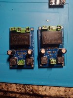
I tought that this small PCB could be useful to whom, like me, already have some original AmyAlice board and want to use a Meanwell encapsulated SMPS with it.
Attachments

Seller gfu-nuernberg on ebay.de sells a large quantity IRM-20-5 and IRM-20-12 for 3.99 Euro a piece. Datecode says 2021. One has to pay double shipping costs when combining but not if one sends a friendly message.
Just a tip. Makes building PSUs a lot cheaper.
Just a tip. Makes building PSUs a lot cheaper.
Hello all, do you have a kit available now that can have IRM-20-5 Meanwell board mounted? In other words IRM-20-5 board mounted and AmyAlice in 1 pcb kit? My app is 5v usb C out from a 220v line. This is for a digital source (Wiim) thank you and best regards.
- Home
- Amplifiers
- Power Supplies
- DC filter for encapsulated SMPS based on AmyAlice design