Hi guys,
I am trying to improve an amp I have here and using this nice chassis/amp as a learning platform. It's a combination of topologies I am vaguely familiar with but don't want to start smoking parts by just diving in. I have been reading about CCS in LTP, no problem by itself with AC coupling to the grids, but this amp has an SRPP (or maybe it's a CCS loaded triode) which is DC coupled to the 6SN7 grids. I have made all the required voltage/current measurements and put them on the schematic. I am planning on an LM334 for the CCS but am open to other suggestions. My main concern is the 93 volts on the tail of the cathodes and the voltage limit of 40 for the LM334. Could I put the LM334 on top of the cathode resistor, maybe drop it to 10K so the 334 has about 10V across it? I am also open to changing the input configuration to something else, maybe another LTP and AC couple it. The 2 input tubes are on a PCB so changing topologies would be a challenge, but not undoable.
Looking forward to learning more about this type of circuit.
Thanks for any help you may be able to offer.
Cheers
PS current in input stage 1.6mA, LTP ~3.5mA per leg
You could use a small pentode instead (6ak5) or EF184. These will work fine with low voltages.
http://valvewizard.co.uk/ccs.html
http://valvewizard.co.uk/ccs.html

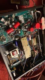
Thanks, and if I were scratch building would consider it but it's limited space under the chassis, I'll attach a few pics. Although looking at it again, I could mount it sideways on a bracket but not sure if there would be enough cooling. ??
Cheers


Cheers
Whatever you do, if you use a true CCS (Constant Current Sink) in the cathodes of the 6SN7, be sure to remember to change the 6SN7 plate load resistors . . .
either use two 47k, or use two 51k resistors. They have to be equal when you use a CCS.
Because you are using global negative feedback, the idea of changing the circuit to have RC coupling between the input stage to the driver stage, that inserts a 3rd low frequency pole (the driver stage to output stage, and the output transformer are the other 2 low frequency poles).
Without proper adjustment of the frequencies of those 3 low frequency poles, you will get Motor-boating oscillations, you can not stack them up to near the same frequencies.
But, if you do RC couple the input to driver stage, then you can use an LM334, LM317, or similar CCS connected directly between the driver parallel cathodes, and the other end of the CCS directly to ground.
Pay particular attention to the Quiescent current and voltage of the 6SN7 (as it is before the modification), and to the range of voltages of those cathodes when the linear range of maximum signal is applied to the amplifier input. A 5V peak signal on the grid of the 6SN7 will cause the cathodes to move about 2.5V.
I am guessing, the 6SN7 has about 3 or 4 mA per triode.
Example of the LM317 as a CCS:
Minimum voltage between input to output pins = 3V
Voltage from output pin to current sense resistor = 1.25V
So the cathodes, when signal is applied, can swing down as far as 4.25V.
And the total cathode current, can be as low as 10mA.
Because of the total cathode current, that might either require a different 6SN7 operating point, or the use of a different CCS, such as an LM334 (Again, check the operating limits of the LM334; versus the limits of the LM317).
Unless you are not satisfied with the sound ofd your amplifier, it probably is not worth the effort of changing the circuit.
But, the easiest change in the world to your amplifier consists of changing from UL operation to Triode Wired mode:
Disconnect the screen resistors from their UL taps, and connect each resistor from the screen to its corresponding plate.
That will have lower power output, lower open loop gain (closed loop gain will remain unchanged), but the amplifier will have more stability, no matter what the load impedance and angle is.
. . . It just might sound as good, or just might sound even better than the original configuration.
Easy to try (listen long, listen carefully, then listen while relaxed).
Happy Listening!
either use two 47k, or use two 51k resistors. They have to be equal when you use a CCS.
Because you are using global negative feedback, the idea of changing the circuit to have RC coupling between the input stage to the driver stage, that inserts a 3rd low frequency pole (the driver stage to output stage, and the output transformer are the other 2 low frequency poles).
Without proper adjustment of the frequencies of those 3 low frequency poles, you will get Motor-boating oscillations, you can not stack them up to near the same frequencies.
But, if you do RC couple the input to driver stage, then you can use an LM334, LM317, or similar CCS connected directly between the driver parallel cathodes, and the other end of the CCS directly to ground.
Pay particular attention to the Quiescent current and voltage of the 6SN7 (as it is before the modification), and to the range of voltages of those cathodes when the linear range of maximum signal is applied to the amplifier input. A 5V peak signal on the grid of the 6SN7 will cause the cathodes to move about 2.5V.
I am guessing, the 6SN7 has about 3 or 4 mA per triode.
Example of the LM317 as a CCS:
Minimum voltage between input to output pins = 3V
Voltage from output pin to current sense resistor = 1.25V
- Burden voltage 3 + 1.25 = 4.25V.
- Minimum specified regulation current is 10mA
So the cathodes, when signal is applied, can swing down as far as 4.25V.
And the total cathode current, can be as low as 10mA.
Because of the total cathode current, that might either require a different 6SN7 operating point, or the use of a different CCS, such as an LM334 (Again, check the operating limits of the LM334; versus the limits of the LM317).
Unless you are not satisfied with the sound ofd your amplifier, it probably is not worth the effort of changing the circuit.
But, the easiest change in the world to your amplifier consists of changing from UL operation to Triode Wired mode:
Disconnect the screen resistors from their UL taps, and connect each resistor from the screen to its corresponding plate.
That will have lower power output, lower open loop gain (closed loop gain will remain unchanged), but the amplifier will have more stability, no matter what the load impedance and angle is.
. . . It just might sound as good, or just might sound even better than the original configuration.
Easy to try (listen long, listen carefully, then listen while relaxed).
Happy Listening!
Last edited:
Thanks boys! Appreciate all the ideas and thank you 6A3sUMMER for the detailed analysis, very informative.
Well working from the bottom of the suggestion list up, I have already changed it to triode mode, see this post in another thread, and made some extensive comparisons and distortion measurements.
Opera M99 to triode
It's not that I am unhappy with the sound, I just know it can be better. My go to reference amp is a pair of Radio Craftsman RC400 that have been thoroughly updated, not modified, just top notch parts and tubes. Then last night my little bone stock Eico HF81 blew my socks off, crap it sounds good. This M99 just doesn't have the clean sparkle or clarity I thought it should have, just a touch of tizz to the cymbals. Perhaps a complete makeover first would be best, changing the couple caps from the WIMA MKP10 to some nice Polycarbonate//PIO combo, and then roll in some more tubes.
The 6AK5 is sounding like the simplest way to make the CCS with the existing first stage. I'm not sure how to get around the 3 low F pole issue if I go to AC coupling.
Back in the 80's I built the old ADI CCDA circuit into one of my ST-70 which was a dead simple circuit using 12AX7 and 6FQ7 both with CCS, which I think is a Noval based 6SN7, it sounded great. I would love to change over the first stage of this M99 to that, requires some board hacking.
I'm running out of typing steam for now.
Look forward to more thoughts.
Cheers
If you would use only 1 CCS in the first stage and a resistor in the second instead then you could omit the coupling cap’s beteeen first and second stage.
So are you suggesting a topology change to the CCDA front end? The schematic of the CCDA I posted is actually a little different than what I used to build, the CCS for the 6FQ7 was a 619R resistor.
And to update a little progress, I cut the trace to the grid of the 6SN7 and C coupled it and no motor boating, but I also didn't put in the CCS yet so normal gain isn't there. I'll put in the LM334 in the morning to see how it works.
Fun fun fun.
cheers
And to update a little progress, I cut the trace to the grid of the 6SN7 and C coupled it and no motor boating, but I also didn't put in the CCS yet so normal gain isn't there. I'll put in the LM334 in the morning to see how it works.
Fun fun fun.
cheers
I just finished installing the LM334 CCS in the 6SN7 stage and it works perfectly. I left the entire amp stock except for reducing the 15K cathode R to 11K, and floated the LM334 on top of that and temporarily put a 50R trimmer to dial in the current and I set the plate volts to the same as the unmodded right channel, 270 volts, and the amp works 100%, cool! I changed the plate loads to 50K and matched them. I just started out slow, brought up the amp slowly with the voltmeter across the LM334 to ensure I wasn't going to exceed its' 40V rating, right now it sits at about 12V across it @ 6.5mA. I played with different current values thru the 6SN7 and it stayed really close to original signal level and distortion even over a 30v plate voltage range.
So far it's been a great learning experience, now I am going to start playing with different caps and tubes to see if I can get rid of the tizz.
Cheers

So far it's been a great learning experience, now I am going to start playing with different caps and tubes to see if I can get rid of the tizz.
Cheers
I used the LM317 as CCS for the long-tail pair circuit. The minimum voltage across it is about 2.5Vdc. You can bias the 6SN7 for about 5~6Vdc.
Please note both of the 6SN7 plate load resistor should be kept the same value of 47K when using CCS in the common cathode circuit.
Johnny
Please note both of the 6SN7 plate load resistor should be kept the same value of 47K when using CCS in the common cathode circuit.
Johnny
kmtang,
The minimum voltage input to output pins of an LM317 is 3V (data sheet).
The voltage across the LM317 current set resistor is 1.25V (data sheet).
That means the minimum voltage across the series circuit CCS of an LM317 and current set resistor is 4.25V.
The voltage of the cathode circuit, including quiescent voltage, and the peak negative signal swing can not go below 4.25V.
Your Mileage May Vary (some LM317 are far better than the data sheet)
I built my own NPN CCS that had a minimum burden voltage of about 2.2V.
1 LED, 3 resistors, 1 NPN, and a positive supply voltage. In addition, there was a 12V zener across that CCS, in case the positive voltage supply was at zero (failed), but with the cathodes still at temperature, the cathodes can easily rise to 12V at low current.
Last edited:
- Home
- Amplifiers
- Tubes / Valves
- DC coupled long tail pair with CCS, need some guidance please