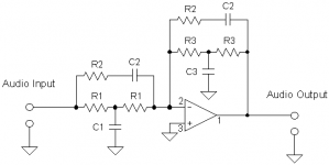
Newbie here. So, I have 'successfully' built a Linkwitz Transform, with a +-10V power supply. I'm using it to extend the frequency response of my home-made desktop speakers.
But I have a problem:
Channel A behaves correctly, but Channel B develops a DC offset at the output, slowly climbing from 0 to 9 volts, and then the sound gets distorted.
It doesn't seem to be caused by a faulty op-amp. They are TL071s, so I swapped them around. The problem remains. It's also not a mishappen contact between the IC pins, as resistance between all adjacent IC pins in channel B is the same as channel A.
What can cause DC buildup in such a simple circuit?
Last edited:
A wiring error?
Do you mean, doing a crappy solder job, or connecting something to the wrong place?
If you mean the later, the power supply is only connected to the circuit by ground, and the opamps' Vcc+ and Vcc- pins. There isn't much to miswire.
If you mean a crappy solder job, I've nudged all the components around, but it doesn't affect the output, so they must be soldered correctly, this time.
What about other bits of the circuit? There is more to a circuit than the power wiring. If you are confident that all is correct, then I am confident that nothing is going wrong. You are more confident in your soldering tests than I am, but then I only have 40 years experience so what do I know? Wiggling can find a bad joint, but it can't confirm a good joint.
Hi,
One thing for sure is one channel is different to the other, and I don't think
it would take DF96 very long to find out what that difference is. So many
people come here saying it doesn't work but they haven't done anything
wrong. 2 out of 3 people here know that is very unlikely to be the case.
😉, sreten.
What about other bits of the circuit? There is more to a circuit than the power wiring. If you are confident that all is correct, then I am confident that nothing is going wrong. You are more confident in your soldering tests than I am, but then I only have 40 years experience so what do I know? Wiggling can find a bad joint, but it can't confirm a good joint.
Sorry for being a newbie, but how do you find the rest of the bad joints?
Topology looked correct the last 25 times I checked, considering re-doing the whole thing...
And what causes tension build-up anyway? Is it some kind of weird opamp thing? Where should I look for it?
Hi,
One thing for sure is one channel is different to the other, and I don't think
it would take DF96 very long to find out what that difference is. So many
people come here saying it doesn't work but they haven't done anything
wrong. 2 out of 3 people here know that is very unlikely to be the case.
😉, sreten.
Hey, I never said I did nothing wrong. I'm smarter than that, and my soldering sucks. Furthermore, the circuit resets (tension buildup disappears) when I twist the circuit board, so I'm pretty sure it's my bad.
What kind of solder are you using Peter?
Using traditional Solder the joints should be smooth, they should not look caked on.
if you are not using lead free solder look for dull (non shiny) joints.
Check these comparisons:
Leads Direct - The Quest for the Perfect Solder Joint
tips:
How to fix a bad solder joint with a solder sucker and solder iron - YouTube
Hey, I never said I did nothing wrong. I'm smarter than that, and my soldering
sucks. Furthermore, the circuit resets (tension buildup disappears) when I twist
the circuit board, so I'm pretty sure it's my bad.
Hi,
That is hardly what you said before implied :
"but it doesn't affect the output, so they must be soldered correctly, this time."
Flexing the board making a difference implies a bad / dry joint.
rgds, sreten.
Yes, either a dry joint or a crack in a PCB trace. If you are using modern lead-free solder then I understand that dry joints and good joints can look identical (I always use the old 'poisonous' solder). If you showed us the circuit we could probably tell you where to look for the problem.
I'd look for an op amp input fed by a capacitor, that also has a resistor to ground, or to some other circuit node that direct current can flow out of.
If that resistor is not properly connected, the small bias current flowing out of the op-amp input charges up the capacitor and hey presto, the very fault you describe.
Probably, learn to solder properly, you've got a dry joint at the end of a resistor. Before you fix it, look at it, see how it looks different from good joints. As DF96 says (and I paraphrase a little) "use proper solder".
As DF96 also says, possibly a crack in a pcb trace. They can be very fine indeed and still be an open circuit. But my money's on a dry joint.
Last edited:
Hi,
Cracks in PCB traces can be obviated by tinning all of the PCB tracks
with solder, but doesn't work that well for high current tracks.
rgds, sreten.
Cracks in PCB traces can be obviated by tinning all of the PCB tracks
with solder, but doesn't work that well for high current tracks.
rgds, sreten.
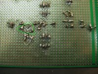
I couldn't find any obvious bad joints, but I "untangled" some blobs where lots of leads met. On the third one the buildup disappeared, and the output is DC-free! 😀
Thanks a lot to everyone, and especially to Simon B. I went untangling the capacitor junctions first. The troubled capacitor was closer to the output, but was a part of the feedback loop. It's the rightmost C2 in the schematic attached.
There are 'before' and 'after' pictures, if anyone's interested.
DF96, sorry for misleading, but I didn't realize at the time. As you can see, the before picture doesn't have obvious 'bad' joints, just lots of evil blobby ones. Guess I underestimated their evilness.
My next project will be adding a high pass filter before the Linkwitz Transform. My speakers have Visaton W170S woofers, and the LT extends them to Q=0.7 and F3=30Hz. They don't do 30Hz like I expected. Distortion is bad, and cone movement is scary with anything except music. My room needs less deep bass anyway.
Going to use a 1st order high pass at 50Hz. If I mess that up, I'm gonna end up with a flat forehead, from a wall. 😀
Attachments

As I said:
A short caused by too much solder in the wrong place is a common fault, often introduced during a 'repair'.
DF96 said:A wiring error?
A short caused by too much solder in the wrong place is a common fault, often introduced during a 'repair'.
- Status
- Not open for further replies.
- Home
- Source & Line
- Analog Line Level
- DC buildup in Linkwitz Transform