I was given this board recently. It looks and works fine, with a +/- 24V supply.
Just curious, which op-amps are used? They are blanked so can not be identified. What is the big secret?
Thanks.
http://www.dact.com/Datasheets/CT101_Datasheet.pdf
Just curious, which op-amps are used? They are blanked so can not be identified. What is the big secret?
Thanks.
http://www.dact.com/Datasheets/CT101_Datasheet.pdf

Or TL 071 or 5534 more likely, since the opamps are not dual I was told.
The previous owner did reach Dact directly some time ago asking, but was advised to send the modules to them for a (costly!) replacement.
The preamp works fine and doesn't need replacements, the question was of an inquisitive nature only if a need ever arises (are they bipolar or FET, so a possible replacement would be easier)
One of the audio big mysteries I guess...🙄
Last edited:
Removing type identifications in audio mostly has a reason. You can guess that reason.
Let me put it this way: if a super duper component is used, there is all reason to show off with that.
(Our philosphy is to only use premium components and BS like that..)
Let me put it this way: if a super duper component is used, there is all reason to show off with that.
(Our philosphy is to only use premium components and BS like that..)
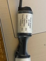
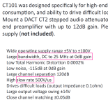
With a max supply of +/-120V and a recommended supply to +/-35V, I wonder what regulators and opamps these are!
If you're curious, measure the supply on the opamp pins.
OTOH, the output specs suggest a regular +/-15 or 17V opamp.
What power supply do you need with these?
Jan
If you're curious, measure the supply on the opamp pins.
OTOH, the output specs suggest a regular +/-15 or 17V opamp.
What power supply do you need with these?
Jan
Last edited:

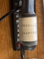
It looks like there are merely pieces of foam tape, and not some sort of paint, covering the part’s identification. Typically, you see the complete sanding off of identifying info., not simply the covering of it. That indicates to me that there is no serious attempt to prevent cloning, simply the attempt to inject some consumer mystery/intrigue as part of the product’s marketing.
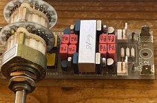
The datasheet linked in post #1 of this thread, shows a PCB whose silkscreen text says "Copyright 1999". The voltage regulators in the datasheet photo appear to be DiodesInc / Zetex "E-Line" packaged bipolar transistors used as series pass devices, with zener diodes setting the BJT base voltage. Then Vout = Vzener - VBE. It's easy to find >200V transistors with good Beta and with excellent Vearly in Zetex's E-Line package.
The 1999 datasheet shows two (singleton) opamps in DIP-8 packages, each opamp has its own pair of voltage regulators. That makes it unlikely that a dual opamp chip like NE5532 or TL072 is used.
Assuming the datasheet is approximately correct and not a collection of complete falsehoods, the claimed slew rate (500 V/usec) is quite high for parts sold in 1999. Neither the 5532 nor the TL072 can meet this spec -- not even close. Similarly, the unity gain bandwidth spec (25 MHz) was not commonplace in 1999.
_
Attachments
The supply on the op-amp pins is either +/- 15 or 18V, can't recall for sure since it had been measured some time ago. Running it off a dual 24V transformer, LM317/337 regulated to a +/- 24V. It works fine really. It is driving Lundahl LL5402 output transformers (SE to BAL) with ease and truly full-range, due to its very low output impedance claimed to be 0,1 Ohm. Something several other line stages failed to achieve, rolling off too early in the LF. That was the main reason for getting it.With a max supply of +/-120V and a recommended supply to +/-35V, I wonder what regulators and opamps these are!
If you're curious, measure the supply on the opamp pins.
OTOH, the output specs suggest a regular +/-15 or 17V opamp.
What power supply do you need with these?
Jan
- Home
- Source & Line
- Analog Line Level
- DACT CT101 op-amps