I have CDR recorder Marantz DR4050 where CDR section is not working due to OPU 24.25 laser failure. CD section is working fine and can be heard in headphone output.
Instead of fixing the laser I am thinking about using that recorder as DAC and headphone amplifier. It has optical, digital and analog inputs to be chosen by a button so I thought that when plugging in a digital sound source it could be heard in headphones. Unfortunately, there is no sound but only displayed message "insert a disc".
I wonder if it could be possible to bypass CDR section or simulate it's working in order to hear source sound in headphones.

Looked at the manual for the CDL4009 and the datasheet for the SAA7392. Looks like the command you would need to change is buried in the I2C comms between the chips. Maybe a small voltage on the HIN pin would be enough to fool the CDR60 chip but I don't know enough about the CDR section to say for certain. It might be possible to do something with the DSA commands but that is not easy either. Easiest thing would be to replace the faulty part.
Thanks for a hint !. I went through whole service manual and it's strange but except that block diagram in post #3 there's no schematics of CDR main board with SAA7392 shown. But assuming I locate that IC - how to put voltage on the HIN pin ? Take a wire (from PSU)and connect positive 12V or negative 8V through a resistor ? How big?
In the meantime I have looked into SA7392 datasheet. HIN is on pin 13 while +3,3V DC is on pin 15 VDDA2. So I could connect pin 15 with pin 13 through a resistor. I have only calculate it's value knowing corrent flowing through.
Do you mean small transformer to get say 5V AC and then decrease that current by a resistor, then one wire to pin 13 and the other to the ground?
Another idea is to get that signal out of CD part. CDR60 will think that It's own laser is working. What do you think?
That may work. The signal at the SAA7324 looks the same as the one at the SAA7392. Focus and all the correction stuff probably won't work but it may be enough.

Last edited:
Fine, but now we should solve how to switch on CD while CDR is working. They can work together only when copying from CD but to do that CDR has to work properly, which it didn't.
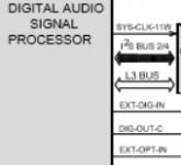
I still think why it is not possible to make MCF5244 ( DASP) working independently.
Another idea is to treat external signal coming to DASP as HF signal and connect e.g EXT-OPT_IN with HFIN.
I still think why it is not possible to make MCF5244 ( DASP) working independently.
Another idea is to treat external signal coming to DASP as HF signal and connect e.g EXT-OPT_IN with HFIN.
Attachments
Generally to make CDR/DAC working by imposing working of CD part is not a good idea. But I suddenly noticed cheap computer or standalone CDR writers. Would it be possible to get an RF signal from such a writer ? I think a schematics would be needed.
Yes... we came to the point we have started from.
I am not the only guy willing to use Marantz DRXXXX recorder as DAC because demand for copying CDs is decreasing. So people are using it as DAC putting a blank CDR, pressing a record buton and letting laser to be on by several hours. This sooner or later damages the OPU and I think that OPU in my recorder was worn out due to the same reason.
OPU in e-bay is ca € 50 but looking on service manual you have to adjust the current which is not simple.
The only solution is to be able to make the DASP = MCF5244 working independently.
I was looking for a schematics of that IC but with no success.
Unless someone reading this topic will have a solution for the DASP we should stop.
You are probably right on stopping. The DASP has parallel address and data busses, I2C and JTAG. Disregarding JTAG, you would have to sniff the I2C bus and maybe the parallel busses. That is a lot of work.
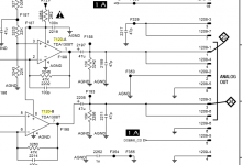
I wanted to use at least Marantz's headphone amplifier as it is playing very well. I have noticed that CD's analog out goes to headphone amplifier IC 7408 = NJM4556D via switch IC7407 = 74HC4053D. So I have connected CDR analog in directly to CDR's CD analog in. When switched power, there's no music heard. You have to initialize it by playing a disk in CD ( maybe it switches IC7407). Then you may take the disk out as the sound from external source connected to CDR analog in is being heard. But..... it's too silent opposite to a sound from CD which I may call "too loud". Don't know why. The sound from CD goes first through ap amp IC7120 = LM833D or TDA1308T ( difference between component list and schematics). But sound from CDR desn't go through LM833D ( IC 7409) in order to go to IC 7408 ( but maybe there's mistake on the drawing) Do you think I should connect CDR analog in directly with pin 3 and 5 of IC 7120 on CD board ?
Attachments
- Status
- Not open for further replies.
- Home
- Source & Line
- Digital Source
- DAC + headphone amplifier based on Marantz DR4050