With the more evolved, optimized CCS version of Trileru, the noise will be improved, and the PSRR and Zout will be even better
Hello Elvee
greetings many thanks for helping me PLEASE can
you post optimised CCS version schematic of
Trileru i can follow the schematic
warm regards
Andrew
Hello Elvee
greetings many thanks for helping me PLEASE can
you post optimised CCS version schematic of
Trileru i can follow the schematic
warm regards
Andrew
That is one of my older discrete designs, it doesn't use LM317.
Here's the simple Denoisator +CCS for 5Vout, for LM317:

You can try LM338 for higher current output.
Here's the simple Denoisator +CCS for 5Vout, for LM317:
You can try LM338 for higher current output.
Last edited:
What Vout do you need? 7.5V?Hi guys,
i have this circuit for my COD dac of twisted pear audio, one for analog and one for digital section set to 7.5Vdc. i want to replace this one and i would like to know which one do you suggest?
thank you! Maxpou
http://www.twistedpearaudio.com/digital/cod.aspx

These should be good values for 7.5Vout. Both configurations, Denoisator on the left and Nonoiser on the right.
You could easily add the Nonoiser to your existing design, just remove the 2.2uF cap and connect the denoiser circuit in its place.

D10 might not be necessary but you could easily add it in the existing circuit.
R12/R18 must be tweaked after you assembled everything, such that you have around 0.4V across C15/C20.
You could probably use R19 at 1K and R24 at 10K as per your circuit but you'd have to recalculate R20 and R18. Q8 can be the BJT you already have. Q5/Q7 can be BC327-25 and Q4/Q6 can be BC337-25.
You can remove R11 (220R) from your schematic. It's there to provide some load to the LM317. Not sure why so much, works out at 34mA for 7.5Vout. The denoiser circuit draws around 5mA, should be enough idle load.
You could easily add the Nonoiser to your existing design, just remove the 2.2uF cap and connect the denoiser circuit in its place.
D10 might not be necessary but you could easily add it in the existing circuit.
R12/R18 must be tweaked after you assembled everything, such that you have around 0.4V across C15/C20.
You could probably use R19 at 1K and R24 at 10K as per your circuit but you'd have to recalculate R20 and R18. Q8 can be the BJT you already have. Q5/Q7 can be BC327-25 and Q4/Q6 can be BC337-25.
You can remove R11 (220R) from your schematic. It's there to provide some load to the LM317. Not sure why so much, works out at 34mA for 7.5Vout. The denoiser circuit draws around 5mA, should be enough idle load.
Attachments
Thank you Trileru, I have some questionsQ5/Q7 can be BC327-25 and Q4/Q6 can be BC337-25.
1- can i replaced this transistors by bc550/560 or bc546/556 because i have a lot of them here?
2- all electrolytic cap are low esr like panasonic fc or not?
3- D7/9 are infrared and not red led?
4- what software can i open the attached document?
thank you! Maxpou
You can use the BC550/BC560 pair, might not have the performance of BC3x7 pair.
Apart from the output cap the electrolytic caps can be any quality, doesn't make a difference. Output cap has to have a 0.2R ESR. Might work with higher, 0.5R for example, but I have only tested with 0.2R.
D7/D9 need to be IR type, 1-1.1Vdrop.
The sim file is for LTSpice.
Apart from the output cap the electrolytic caps can be any quality, doesn't make a difference. Output cap has to have a 0.2R ESR. Might work with higher, 0.5R for example, but I have only tested with 0.2R.
D7/D9 need to be IR type, 1-1.1Vdrop.
The sim file is for LTSpice.
Do i need a high HFE like 550C/560C? thank you! MaxpouYou can use the BC550/BC560 pair
Using high gain Q4/Q6 will make for a high R12/R18, and will not be practical to tweak to needed value.
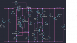
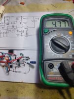
Hello Trileru
greetings a quick point to point wiring of the above schematic VOLTAGE
out 4.8 volts what resistor to change to increase voltage to 5 volt
warm regards
Andrew
greetings a quick point to point wiring of the above schematic VOLTAGE
out 4.8 volts what resistor to change to increase voltage to 5 volt
warm regards
Andrew
Attachments
You adjust Vout with R3, but do that with D3/C5 disconnected. After you set Vout connect C5 only and tweak R1 value until you have about 50-100mV across C5 (negative side o cap towards denoiser). Then connect D3 and should be fine, and startup swing should be pretty low.
I think 250mW should be fine. The load resistor I have on the output of the regulator on all sim files are to simulate around 100mA current draw. That resistor should not be designed into a pcb.
Salut Trileru,
can i replace the IR led because it's very expensive for led with 1-1.1 volt drop? thank you Maxpou
can i replace the IR led because it's very expensive for led with 1-1.1 volt drop? thank you Maxpou
Hi,
i would like to know if the manufacturer is very important for regulator because i have some vishay lm317 here? thank you!Maxpou
i would like to know if the manufacturer is very important for regulator because i have some vishay lm317 here? thank you!Maxpou
You can't replace the IR LED. You could try and source it from older TV remotes. Or as Elvee mentioned you could use the IR LED in an optocoupler. Maybe cut the other two pins from the package so they won't interfere with other parts.
In my tests there wasn't much if any difference between different manufacturers of LM317 but my sample size was small, so there's always room for surprises.
In my tests there wasn't much if any difference between different manufacturers of LM317 but my sample size was small, so there's always room for surprises.
TV, CD Player, DVD player, Cable box remotes. I found quite a few old remotes lurking around the house and they all had IR LED's and all of mine measured 1.1V or very close.
The index is (provisionally) complete. If you notice errors or omissions, or have additional remarks, please mention them, I will edit the index accordingly
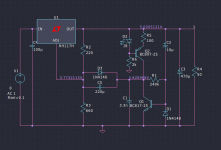
This post is meant to be linked in this thread's index and I will explain my contribution to the denoiser circuit.
Let’s start by showing how exactly my version differs from the original Denoisator:

On the left side is the original Denoisator, on the right side is my version with the CCS and startup swing limiter. I have replaced R5 resistor with the CCS made up of R11/R12/D3/Q3.
I have removed R6 and reduced Q2’s base startup surge with a higher C8 output cap. 470uF-1000uF seems to cover most cases and reduces the base current surge to a manageable value.
R6’s noise contribution starts to matter at the noise levels the Denoisator/Nonoiser are capable of so I tried to work around it.
D4 is the startup swing limiter, can be any type of diode as long as the resulting Vdrop is adequate for any particular Vout. I will later on explain how to decide each part’s value based on Vout.
As you notice on my version I chose a higher Q2 Vce operating point since empirically it seemed to require the least compensation to be stable. This comes with the major drawback that startup swing radically increases even hitting Vin-1.25V values. That’s not so great so I used D4 diode to limit this initial swing to very low values. Basically the denoiser is DC-coupled to Vadj at startup and then moves into an AC-coupled state after it settles.
This arrangement works fine for the negative LM337 as well, just swap all polarized parts and also swap BJTs with complementary.
For higher output current you can use LM338 instead of LM317. Earlier tests showed minimal PSRR/noise performance degradation at higher output current (I think I tested at around 3.5Aout).
There’s also a sort of hybrid you could use but I never tested this:

The left circuit is the original Denoisator and on the right is the hybrid. It uses the same ~Vadj Q4 Vce but without the CCS. Protection resistor (R6) is also removed.
This has the advantage of being simpler than the CCS version but also having lower startup swing vs original Denoisator (Vout=15V in the following example):

But I never tested this version, I don’t know how it behaves in practice.
Also another offshoot circuit that I also find interesting (and have built and tested) is the DC-coupled Denoisator:

As you see I did away with the classical LM317 Vout setting resistors and instead Vout is set by Vce of Q2.
This results in this type of (pretty serious) performance:

The circuit performs extremely well for what it is, tho it does have two drawbacks. Tempco is very poor, Vout will vary by quite a bit. For 12-15Vout you might have a decrease of even 2V depending on operating temperature. In some cases this might not be an issue (say for some opamps power) so it’s quite usable in (some) audio.
The other one is that Vout is set by a semiconductor. If that goes then Vout can go very low or max out at Vin-1.25V.
If you want this type of performance with better tempco then we move to the last version namely the NoNoiser. Here’s a comparison between it and my version with CCS:

Left side is the original NoNoiser, hopefully I didn’t leave anything out (apart from an optional resistor that I didn’t copy).
Main differences are the CCS, I removed R14 protection resistor as in the previous versions. I also lowered C9 coupling cap from 220uF to 22uF.
I don’t use the ferrite bead. Actually seems to create some issues with CCS and higher Vce of Q5.
C6 can be also lowered since R9 value increases by 4 times.
Also the presence of D6 startup swing limiter.
PSRR performance improvement seems decent:

Some HF performance degrading due to the 3.3n compensation cap, where the original NoNoiser uses the ferrite bead instead.
Startup swing is lower, almost doesn’t exist:

Noise floor levels should be around 1-2nV/sqrtHz (or ~150nV-300nV total noise in audio band) for the Denoisator+CCS version to around 250-500pV/sqrtHz (or ~ 36-70nV total in audio band) for NoNoiser+CCS or DC-coupled Denoisator.
This concludes the overview of my contributions to this project, as far as the circuits go.
The short of it is that if you want a low noise supply with decent PSRR then just make the original Denoisator or Denoisator +CCS. Plenty performance at a low cost/complexity.
If you don’t know why you’d need the NoNoiser instead of the Denoisator then just build the Denoisator. I think the NoNoiser is overkill for most things.
When I get the chance I'll make some more posts where I’ll explain how to choose each part value depending on needed Vout, and I’ll also post/overview the pcb designs I made.
edit: simulation PSRR values will be a bit lower in practice, RH117 performance is not accurate for a regular LM317.
Let’s start by showing how exactly my version differs from the original Denoisator:
On the left side is the original Denoisator, on the right side is my version with the CCS and startup swing limiter. I have replaced R5 resistor with the CCS made up of R11/R12/D3/Q3.
I have removed R6 and reduced Q2’s base startup surge with a higher C8 output cap. 470uF-1000uF seems to cover most cases and reduces the base current surge to a manageable value.
R6’s noise contribution starts to matter at the noise levels the Denoisator/Nonoiser are capable of so I tried to work around it.
D4 is the startup swing limiter, can be any type of diode as long as the resulting Vdrop is adequate for any particular Vout. I will later on explain how to decide each part’s value based on Vout.
As you notice on my version I chose a higher Q2 Vce operating point since empirically it seemed to require the least compensation to be stable. This comes with the major drawback that startup swing radically increases even hitting Vin-1.25V values. That’s not so great so I used D4 diode to limit this initial swing to very low values. Basically the denoiser is DC-coupled to Vadj at startup and then moves into an AC-coupled state after it settles.
This arrangement works fine for the negative LM337 as well, just swap all polarized parts and also swap BJTs with complementary.
For higher output current you can use LM338 instead of LM317. Earlier tests showed minimal PSRR/noise performance degradation at higher output current (I think I tested at around 3.5Aout).
There’s also a sort of hybrid you could use but I never tested this:
The left circuit is the original Denoisator and on the right is the hybrid. It uses the same ~Vadj Q4 Vce but without the CCS. Protection resistor (R6) is also removed.
This has the advantage of being simpler than the CCS version but also having lower startup swing vs original Denoisator (Vout=15V in the following example):
But I never tested this version, I don’t know how it behaves in practice.
Also another offshoot circuit that I also find interesting (and have built and tested) is the DC-coupled Denoisator:
As you see I did away with the classical LM317 Vout setting resistors and instead Vout is set by Vce of Q2.
This results in this type of (pretty serious) performance:
The circuit performs extremely well for what it is, tho it does have two drawbacks. Tempco is very poor, Vout will vary by quite a bit. For 12-15Vout you might have a decrease of even 2V depending on operating temperature. In some cases this might not be an issue (say for some opamps power) so it’s quite usable in (some) audio.
The other one is that Vout is set by a semiconductor. If that goes then Vout can go very low or max out at Vin-1.25V.
If you want this type of performance with better tempco then we move to the last version namely the NoNoiser. Here’s a comparison between it and my version with CCS:
Left side is the original NoNoiser, hopefully I didn’t leave anything out (apart from an optional resistor that I didn’t copy).
Main differences are the CCS, I removed R14 protection resistor as in the previous versions. I also lowered C9 coupling cap from 220uF to 22uF.
I don’t use the ferrite bead. Actually seems to create some issues with CCS and higher Vce of Q5.
C6 can be also lowered since R9 value increases by 4 times.
Also the presence of D6 startup swing limiter.
PSRR performance improvement seems decent:
Some HF performance degrading due to the 3.3n compensation cap, where the original NoNoiser uses the ferrite bead instead.
Startup swing is lower, almost doesn’t exist:
Noise floor levels should be around 1-2nV/sqrtHz (or ~150nV-300nV total noise in audio band) for the Denoisator+CCS version to around 250-500pV/sqrtHz (or ~ 36-70nV total in audio band) for NoNoiser+CCS or DC-coupled Denoisator.
This concludes the overview of my contributions to this project, as far as the circuits go.
The short of it is that if you want a low noise supply with decent PSRR then just make the original Denoisator or Denoisator +CCS. Plenty performance at a low cost/complexity.
If you don’t know why you’d need the NoNoiser instead of the Denoisator then just build the Denoisator. I think the NoNoiser is overkill for most things.
When I get the chance I'll make some more posts where I’ll explain how to choose each part value depending on needed Vout, and I’ll also post/overview the pcb designs I made.
edit: simulation PSRR values will be a bit lower in practice, RH117 performance is not accurate for a regular LM317.
Last edited:
- Home
- Amplifiers
- Power Supplies
- D-Noizator: a magic active noise canceller to retrofit & upgrade any 317-based VReg