Here's another application of the simple denoiser + CCS and startup swing limiter mod, used in my ADC on all rails. +/-12V for opamps, 5V for VACC and 3.3V for digital. I didn't use the nonoiser block as I didn't really need the extra gain, I had capacitance multipliers on all three rails (+/- for analog and + for digital).
The end result for my CS5361 ADC is this:

I originally made a design mistake in my ADC on digital side, because I didn't carefully read the datasheet🤦♂️ and put the clock next to the FILT+ line of the ADC. That resulted in having this on the ADC's input:

And those peaks at around 2kHz can be seen in previous measurements. What tipped me off was that they'd change frequency a bit while touching either XO either FILT+ line. Luckily I made provisions in the design for both DAC and ADC so I can feed DAC's clock to ADC.
That clears up that crap but adds the 50Hz pickup because of the external coax running to the ADC board. Also ADC is without a case atm.
So the virtual noise with a 60dB LNA, from the ADC, is around 15nV in the audio band, which is pretty nice for what I need it for.
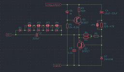
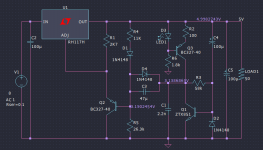
The exact schematic used throughout the ADC is this:

This is the +12V rail. In reality R1 is 470K, that's how it worked out for the DC values in the picture.
In the case of 5V and 3.3V D3 is a 1n4148 diode, instead of the RED led used for +/-12V. Initial swings are irrelevant for all rails, but you do need to tweak R1. D2 is IR LED for all rails.
C2 is 47uF for 5V and 3.3V. If you use for C3 output cap 470uF for all Vout you don't need the series protection resistor for C2. Surge current into base of Q1 is about 70mA:

And lasts under 1ms, for which BC817 is specced at a max of 200mA at 25 degrees C. Previous design I used was hammered at 200mA and they (BJTs) seemed to have made it through. They should be ok from now on.
So try to find 470uF output cap in voltage rating and ESR (~200mOhm) for your Vout.
C1 was 5n for every denoiser just to make sure and everything seemed stable and recovered fast when poking at it.
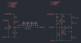
The ADC frontend is a bit different from datasheet:

The two stages are DC coupled and result in a gain of 1. This way I was able to tie that middle point to VACC instead of VQ pin (ADC internal VACC/2), which I think had higher noise output vs 5Vout denoiser. It also has a high output impedance and can source very low current.
I used OPA827 for first stage and NE5534A for second one which works fine for measuring noise. If measuring distortion maybe replace NE5534A with something else.
The other channel was designed (out of pure curiosity) with dual opamps, and I used NE5532 for both stages. The result is not impressive but still very usable.
This frontend should work well for the bit better CS5381.
So in conclusion the nonoiser is a bit extreme and adds a weakness to the DC output point reliability. If the nonoiser BJT fails for any reason then Vout changes and might ruin whatever it powers. I'd use it if you absolutely need the extra PSRR. The simple denoiser + CCS works fine even for 5V for VACC.
The end result for my CS5361 ADC is this:
I originally made a design mistake in my ADC on digital side, because I didn't carefully read the datasheet🤦♂️ and put the clock next to the FILT+ line of the ADC. That resulted in having this on the ADC's input:
And those peaks at around 2kHz can be seen in previous measurements. What tipped me off was that they'd change frequency a bit while touching either XO either FILT+ line. Luckily I made provisions in the design for both DAC and ADC so I can feed DAC's clock to ADC.
That clears up that crap but adds the 50Hz pickup because of the external coax running to the ADC board. Also ADC is without a case atm.
So the virtual noise with a 60dB LNA, from the ADC, is around 15nV in the audio band, which is pretty nice for what I need it for.
The exact schematic used throughout the ADC is this:
This is the +12V rail. In reality R1 is 470K, that's how it worked out for the DC values in the picture.
In the case of 5V and 3.3V D3 is a 1n4148 diode, instead of the RED led used for +/-12V. Initial swings are irrelevant for all rails, but you do need to tweak R1. D2 is IR LED for all rails.
C2 is 47uF for 5V and 3.3V. If you use for C3 output cap 470uF for all Vout you don't need the series protection resistor for C2. Surge current into base of Q1 is about 70mA:
And lasts under 1ms, for which BC817 is specced at a max of 200mA at 25 degrees C. Previous design I used was hammered at 200mA and they (BJTs) seemed to have made it through. They should be ok from now on.
So try to find 470uF output cap in voltage rating and ESR (~200mOhm) for your Vout.
C1 was 5n for every denoiser just to make sure and everything seemed stable and recovered fast when poking at it.
The ADC frontend is a bit different from datasheet:
The two stages are DC coupled and result in a gain of 1. This way I was able to tie that middle point to VACC instead of VQ pin (ADC internal VACC/2), which I think had higher noise output vs 5Vout denoiser. It also has a high output impedance and can source very low current.
I used OPA827 for first stage and NE5534A for second one which works fine for measuring noise. If measuring distortion maybe replace NE5534A with something else.
The other channel was designed (out of pure curiosity) with dual opamps, and I used NE5532 for both stages. The result is not impressive but still very usable.
This frontend should work well for the bit better CS5381.
So in conclusion the nonoiser is a bit extreme and adds a weakness to the DC output point reliability. If the nonoiser BJT fails for any reason then Vout changes and might ruin whatever it powers. I'd use it if you absolutely need the extra PSRR. The simple denoiser + CCS works fine even for 5V for VACC.
Last edited:
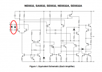
Naah, R5 and R44, plus the fact that the noninverting inputs of U2A and U2B are connected to ground, mean that the on-chip protection diodes of the 5532 {circled in red} will handily swallow any overvoltage or undervoltage at the inputs, without excessively huge clamping currents.
_
_
Attachments
Worked fine throughout my measurements. R5/R44 don't contribute that much noise. I don't need it lower anyway.
If you're talking about the input impedance my LNA is ok with it.
User googlyone used something similar here:
https://www.diyaudio.com/archive/bl...udio-analyser-using-cs4398-cs5381-cs5361.html
But he did add another buffer to increase input impedance. He seemed pretty happy with the result.
User googlyone used something similar here:
https://www.diyaudio.com/archive/bl...udio-analyser-using-cs4398-cs5381-cs5361.html
But he did add another buffer to increase input impedance. He seemed pretty happy with the result.
A cascade of two LM317's requires nine components (4*R, 3*C, 2*LM317) and suppresses 60Hz and related harmonics by 120 dB.
Both the Denoisator and NoNoiser are Elvee's designs, I merely optimized them with the CCS and startup swing limiter.
I'll make a sim file with both for your Vout.
You could maybe use 2xLM317 as Mark Johnson said but I'd use one for current limiting if I'd have the extra space for it.
I'll make a sim file with both for your Vout.
You could maybe use 2xLM317 as Mark Johnson said but I'd use one for current limiting if I'd have the extra space for it.
Here's a first draft for 21Vout but I don't know Vin.

You'd need to consider Q1/Q3 as there's around 130mW dissipated. Maybe use a TO92 part such as LM337.
Also RH117 is lower current than LM317, I used a lighter load for the sim.
edit: PSRR is lower for LM317.
You'd need to consider Q1/Q3 as there's around 130mW dissipated. Maybe use a TO92 part such as LM337.
Also RH117 is lower current than LM317, I used a lighter load for the sim.
edit: PSRR is lower for LM317.
Attachments
Last edited:
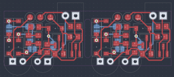
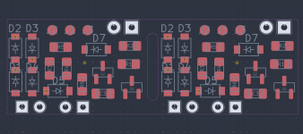
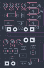
I remade the add-on boards to include the CCS and startup swing limiter.
There's a string of 5x SOD-123 1n4148 footprints in parallel with the denoiser output coupling cap. 4 of them have SMD jumpers on the backside. I also included the input capacitor series protection resistor which also has a SMD jumper on the backside.
CCS LED should be IR type. A good source for these should be old remotes. As long as it measures around 1-1.1Vdrop on DMM it should be good.
Denoiser resistor is made of two parallel resistors in series with another resistor, should allow to tweak the value precisely.
Use BC8x7-25 for denoiser BJT. Higher gain ones require a high resistor value and performance is similar to lower gain ones. You can use the higher gain ones for CCS BJT, doesn't matter in that spot.
I made the PCB for two identical boards with a slot between them so you can more easily snap them if you only need one. Schematic/photos are for the positive rail. For negative rail swap BJTs and rotate all polarized parts.
Best to construct the LM3x7 regulators on breadboard with same Vout as your final application. Connect the add-on board and tweak the resistor value, after everything checks out you install it in the final application.
The diode string should allow for up to 24Vout, or even more if you manage to fit SMD LEDs on the diode's footprints. But you should be able to get away with 5x1n4148 up to 24Vout.
Also maybe add some kapton tape on the backside over the SMD jumpers, before installing the electrolytic caps. I offset the jumpers a bit to allow the capacitors to sit flush with the pcb.
Connectors are SMD pads to not interfere with the capacitors on the backside.
This version is for fab house only, bit harder to fit all options for DIY. I have not tested this design so you make it at your own risk.
Attachments
-
 Screenshot_20220906_131807.png97.2 KB · Views: 445
 -
 Screenshot_20220906_131902.png98.1 KB · Views: 338
 -
 Screenshot_20220906_132218.png82.5 KB · Views: 327
 -
 Screenshot_20220906_132330.png47 KB · Views: 318
 -
 Screenshot_20220906_132422.png47.6 KB · Views: 315
 -
 Screenshot_20220906_132637.png21.7 KB · Views: 434
 -
 Screenshot_20220906_173740.png10.5 KB · Views: 446
 -
denoiser.zip154.8 KB · Views: 197
Last edited:
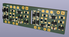
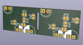
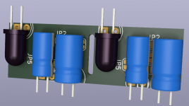
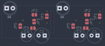
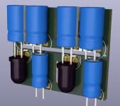
This post if for the Nonoiser add-on boards I used in my headphone amp. These can be DIY-ed and also have two output coupling capacitors back to back. Shouldn't be needed but the second one fits on the board and theoretically it should be safer with two.
Boards are double, all have silkscreen for positive rail, you choose which side you use for negative and rotate all polarized parts and swap BJTs. These can be split up as well, I added all that's needed for two rails. You should split them horizontally but vertically only if you need only one.
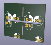
There's 5x1n4148 SOD-123 series diode footprints in parallel with the output back-to-back coupling capacitors. There's jumpers on the topside to bypass the ones you are not using. You should also be able to hack in SMD LEDs on those footprints.
Install the upper boards next to the regulator, they set Vout.
Don't forget to replace the 120R-240R resistor from the original application you are modding, with a 2.7K resistor. Also make sure the output capacitor is at least 470uF. The protection resistor doesn't have a bypass jumper but you can install a 0R 0805 resistor if you want to bypass it.
Lower boards are the denoiser itself. Try to sense Vout closer to the regulator and keep the wires short and close. Then run the DNZ wire to the board that sets Vout, on its DNZ pad.
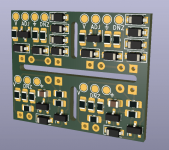
This pcb design is tested on my headphone amp and works fine as long as you use the correct values.
Also add the LM3x7 datasheet protection diodes to whatever you are modding, somehow.
To recap:
Latest full LM3x7 DC coupled Denoisator PCB designs: https://www.diyaudio.com/community/...-317-based-v-reg.331491/page-123#post-7076972
Latest full LM3x7 Nonoiser (AC-coupled) PCB designs: https://www.diyaudio.com/community/...-317-based-v-reg.331491/page-124#post-7090788
Hopefully the fab house doesn't complain about the slots.
Boards are double, all have silkscreen for positive rail, you choose which side you use for negative and rotate all polarized parts and swap BJTs. These can be split up as well, I added all that's needed for two rails. You should split them horizontally but vertically only if you need only one.
There's 5x1n4148 SOD-123 series diode footprints in parallel with the output back-to-back coupling capacitors. There's jumpers on the topside to bypass the ones you are not using. You should also be able to hack in SMD LEDs on those footprints.
Install the upper boards next to the regulator, they set Vout.
Don't forget to replace the 120R-240R resistor from the original application you are modding, with a 2.7K resistor. Also make sure the output capacitor is at least 470uF. The protection resistor doesn't have a bypass jumper but you can install a 0R 0805 resistor if you want to bypass it.
Lower boards are the denoiser itself. Try to sense Vout closer to the regulator and keep the wires short and close. Then run the DNZ wire to the board that sets Vout, on its DNZ pad.
This pcb design is tested on my headphone amp and works fine as long as you use the correct values.
Also add the LM3x7 datasheet protection diodes to whatever you are modding, somehow.
To recap:
Latest full LM3x7 DC coupled Denoisator PCB designs: https://www.diyaudio.com/community/...-317-based-v-reg.331491/page-123#post-7076972
Latest full LM3x7 Nonoiser (AC-coupled) PCB designs: https://www.diyaudio.com/community/...-317-based-v-reg.331491/page-124#post-7090788
Hopefully the fab house doesn't complain about the slots.
Attachments
-
nonoiser add-on.zip172.6 KB · Views: 154
-
 Screenshot_20220907_172707.png23.9 KB · Views: 321
 -
 Screenshot_20220907_172647.png122.5 KB · Views: 290
 -
 Screenshot_20220907_172553.png10.7 KB · Views: 225
 -
 Screenshot_20220907_172322.png15.2 KB · Views: 264
 -
 Screenshot_20220907_171559.png113.1 KB · Views: 268
 -
 Screenshot_20220907_170730.png125.9 KB · Views: 293
 -
 Screenshot_20220907_170623.png134.2 KB · Views: 317
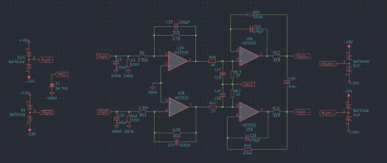
I changed the input stage configuration to a non-inverting amplifier. Higher input impedance and same gain overall. Did not make a difference noisewise. Using a buffer would increase the noise 4x.Naah, R5 and R44, plus the fact that the noninverting inputs of U2A and U2B are connected to ground, mean that the on-chip protection diodes of the 5532 {circled in red} will handily swallow any overvoltage or undervoltage at the inputs, without excessively huge clamping currents.
_
The new input stage is on the right:
And the result, grounded input:
And noise of 120R resistor:
And noise of grounded LNA (+ADC):
Overall yeah I guess this would be a superior version with the high input impedance.
I also made a distortion measurement for this ADC.

Datasheet states a THD+N of -105dB and worst case -99dB (96kHz). I guess it's ok?
I did replace the output stage opamps from NE5534A to the same OPA827 of the input stage. But didn't seem to make a difference noise or distortion wise.
I also measured the headphone amp I modded with the nonoiser and seems it doesn't add anything, maybe 0.5dB worse for THD+N, but it's basically transparent (with input from DAC).
Last edited:
I have started the creation of an index; it is at the bottom of the first post.
It is just the beginning (I am at the page 30), but if you notice errors or omissions, please mention them.
Suggestions are welcome too.
It is just the beginning (I am at the page 30), but if you notice errors or omissions, please mention them.
Suggestions are welcome too.

Hello Elvee
greetings which schematic for 5 volt dc output
i want to build it for my mp3 module
warm regards
Andrew
greetings which schematic for 5 volt dc output
i want to build it for my mp3 module
warm regards
Andrew
There are a number of options: one would be a LM317 with a regular denoiser, with component values adapted for 5V.
This would look like this:

Another option is a Dienoiser combined with a 7805; simple and straightforward (see here: https://www.diyaudio.com/community/...grade-any-317-based-v-reg.331491/post-6022136 ).
For the ultimate performance, you could turn to the nonoiser or one of Trileru's variations, but I don't think it is necessary: it would be overkill, and demanding regarding layout, etc.
Edit: with the modified resistor value, C2 should not exceed 4.7µF, otherwise the VLF peaking becomes really intrusive; 2µ2 or 3µ3 would be fine and would have a small impact on subsonic correction properties
This would look like this:
Another option is a Dienoiser combined with a 7805; simple and straightforward (see here: https://www.diyaudio.com/community/...grade-any-317-based-v-reg.331491/post-6022136 ).
For the ultimate performance, you could turn to the nonoiser or one of Trileru's variations, but I don't think it is necessary: it would be overkill, and demanding regarding layout, etc.
Edit: with the modified resistor value, C2 should not exceed 4.7µF, otherwise the VLF peaking becomes really intrusive; 2µ2 or 3µ3 would be fine and would have a small impact on subsonic correction properties
Last edited:
What is the maximum value of C5 that this circuit can handle? Can a supercap of a couple of Farads be used for a 5VDC 1 Ampere DAC supply? Thanks.There are a number of options: one would be a LM317 with a regular denoiser, with component values adapted for 5V.
This would look like this:
View attachment 1095001
Another option is a Dienoiser combined with a 7805; simple and straightforward (see here: https://www.diyaudio.com/community/...grade-any-317-based-v-reg.331491/post-6022136 ).
For the ultimate performance, you could turn to the nonoiser or one of Trileru's variations, but I don't think it is necessary: it would be overkill, and demanding regarding layout, etc.
Edit: with the modified resistor value, C2 should not exceed 4.7µF, otherwise the VLF peaking becomes really intrusive; 2µ2 or 3µ3 would be fine and would have a small impact on subsonic correction properties
- Home
- Amplifiers
- Power Supplies
- D-Noizator: a magic active noise canceller to retrofit & upgrade any 317-based VReg