Hi,
I am planning to build a f2j for my openbafle speaker. Looking to biamp the system with a current source amplifier. One possible way might beto connect a resistor in series and take the feedback from the resistor. Just wondering if anybody tried that before.
Oon
Sent from my MB860 using Tapatalk
I am planning to build a f2j for my openbafle speaker. Looking to biamp the system with a current source amplifier. One possible way might beto connect a resistor in series and take the feedback from the resistor. Just wondering if anybody tried that before.
Oon
Sent from my MB860 using Tapatalk
Hi,
The reason is firstwatt f2j is a current drive amplifier intended for fullrange amplifiers. Voltage driven speakers have one weakness, that is the forces acting on the cone is no longer representative of the true signal since the current is no longer proportional to the voltage because of inductance, back emf etc. So the idea of a current amp is to match the f2j.
I am a bit worried about instability though..
Oon
Sent from my MB860 using Tapatalk
National Semi's data sheet notwithstanding -- you can turn a chipamp into a Howland current source.
Voltage driven speakers have one weakness, that is the forces acting on the cone is no longer representative of the true signal since the current is no longer proportional to the voltage
Most speakers are designed to have a nearly flat frequency response for constant voltage. And they are all current-driven.
Look at the impedance graph of a speaker. Then use Ohm's law (U = I x R) to find out how the voltage will look, when you apply constant current instead of constant voltage. The frequency response will become a scaled image of the impedance curve added to the frequency response for constant voltage.
The amplifier would already be clipping at low volumes, where the impedance is high, e.g. around the speaker's resonant frequency, at very high frequencies, around crossover frequencies, etc., because increased impedance demands increased voltage to achieve a constant current.
Of course the F2J is not actually keeping the current constant. It works more like a shunt regulator, where a constant current is shared among the (MOSFET) transistor and the speaker. It deviates just enough current into the speaker to achieve a certain voltage at the speaker terminals. In the end you still have a voltage controlled speaker.
Last edited:
Been there, done that a year ago. I've got a LM3886 amp in a classic V-I configuration. For best results, you need to ensure the speaker impedance is as flat as possible and/or use a series crossover. I use a fullrange driver with mine with a zobel to level out the impedance and avoid the complexity of a crossover. Watch out for the impedance spike at resonance frequency, it can cause clipping.
Dear pacific blue,
Disagree on the voltage control speaker part the F2. What is important the current is proportional to the input voltage. Because the current bleeding by the mosfet is proportional to the input voltage. So in that sense the speaker is current controlled.
There is however a 16 ohm resistor in parallel so at resonance, the amplifier is essentially voltage amplifier.
Oon
Sent from my MB860 using Tapatalk
Sent from my MB860 using Tapatalk
Dear fenris,
Do you mind sharing a bit more on the details of your circuit. Did you just put the speaker in between the output and the -inverting input. And a 1 ohm between the inverting input and the ground? Or maybe an additional voltage divider?
I actually planned for it for woofer use in an open baffle, so it needs plenty of equalization anyway. The additional boost attacks resonance could come in handy since I need a bit of boost at fs anyway.
I am just thinking the phase relationship between woofer and the fullrange will be better.
How do you like the sound compared to normal voltage amps?
Oon
the current bleeding by the mosfet is proportional to the input voltage.
No. If the output current was proportional to the input voltage you would get a frequency response that looks like the impedance curve. The current is proportional to the output voltage divided by the load impedance.
The F2 is a voltage regulator like any other audio power amp. The output voltage is proportional to the input voltage, controlled by voltage feedback through P1, R4, R5 and R6.
The difference to most other amps is that the F2 has less stages. It combines the functions of the typical three stages in one. You find, what Pass calls 'active current source', in most amps' VAS (voltage amplification stage). In the F2 there is simply no additional output (buffer) stage that makes the load for the VAS lighter and more constant.
I'm using specifically shaped output impedance to drive transducers for quite a while now as the answer to the old question of wether voltage drive is better than current drive. No simple answers here.
Not necessarily pure current drive is the optimum for any given transducer, neither is standard voltage drive (driver terminated with its own Re) nor full feedback (driver terminated with something as low as Re/10 by setting an output impedance of -9/10Re). Rather, one usually can find a complex drive impedance profile (DIP) that gets the most out of the driver in the given situation.
For any comparison (and any working solution) you *must* EQ either the feedback signal or the input signal to obtain identical SPL responses no matter what DIP is dialed in via the feeback network.
I tend to do this pre-EQ with DSP processing for convenience, forcing the driver's terminal voltage to common target regardless of any impedance tricks employed.
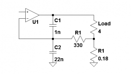
BTW, For current drive (with chipamps), Howland current pumps are not required unless you *must* reference one terminal to ground for some obscure reason. A shunt in the ground return does exactly the same thing from a circuit analysis standpoint.
I've been using circuits as simple as shown (not showing Zobel and Load stabilizing networks). It gives a Zout equal to that of a small series capacitor (2uF) which is close enough to "pure" current drive. At 10kHz |Zout| is about 8Ohms, increasing 10x for every decade you go lower in frequency
- Klaus
Not necessarily pure current drive is the optimum for any given transducer, neither is standard voltage drive (driver terminated with its own Re) nor full feedback (driver terminated with something as low as Re/10 by setting an output impedance of -9/10Re). Rather, one usually can find a complex drive impedance profile (DIP) that gets the most out of the driver in the given situation.
For any comparison (and any working solution) you *must* EQ either the feedback signal or the input signal to obtain identical SPL responses no matter what DIP is dialed in via the feeback network.
I tend to do this pre-EQ with DSP processing for convenience, forcing the driver's terminal voltage to common target regardless of any impedance tricks employed.
BTW, For current drive (with chipamps), Howland current pumps are not required unless you *must* reference one terminal to ground for some obscure reason. A shunt in the ground return does exactly the same thing from a circuit analysis standpoint.
I've been using circuits as simple as shown (not showing Zobel and Load stabilizing networks). It gives a Zout equal to that of a small series capacitor (2uF) which is close enough to "pure" current drive. At 10kHz |Zout| is about 8Ohms, increasing 10x for every decade you go lower in frequency
- Klaus
Attachments
You'll need a driver with excellent linearity of the spider/surround as with current drive there is no feedback in the driver to linearize it, and with as linear a motor you can find, to start with. Also, aluminum formers are a good choice to provide some stable mechanical damping, otherwise chaotic movement may show up ("jump resonance").I actually planned for it for woofer use in an open baffle
My experience with pure current drive of rather good pro woofers in open baffle were disappointing. You need stable conditions ("nailed" T/S-parameters) for current drive, and the stronger the impedance peaks of the driver the more so.
No. If the output current was proportional to the input voltage you would get a frequency response that looks like the impedance curve. The current is proportional to the output voltage divided by the load impedance.
The F2 is a voltage regulator like any other audio power amp. The output voltage is proportional to the input voltage, controlled by voltage feedback through P1, R4, R5 and R6.
t.
Hi pacific blue. Pass clearly states in the manual it is a current amplifier. Transconductance. It looks like a voltage amp but it behaves differently. The feedback loop is only for DC. AC wise. Vg is just Vin. There is no feedback. Vs is same as Vin. And Id is just Vs/r6-r12. That is where the conversion from v to I takes place.
And yes, it will have weird frequency responses. Which is why you need a impedance compensation network for each individual speaker. Which can be found in the manual of f1 for various lowther and fostex model. That is why Pass said clearly this amp is not for everyone...
F3 to F5 are voltage amps.
Sent from my MB860 using Tapatalk
Speaker Dave suplied this link in the can't tuna fish thread. It's not a curent source
amp but a variable impedience amp.
Variable Amplifier Impedance
amp but a variable impedience amp.
Variable Amplifier Impedance
You'll need a driver with excellent linearity of the spider/surround as with current drive there is no feedback in the driver to linearize it, and with as linear a motor you can find, to start with. Also, aluminum formers are a good choice to provide some stable mechanical damping, otherwise chaotic movement may show up ("jump resonance").I actually planned for it for woofer use in an open baffle
My experience with pure current drive of rather good pro woofers in open baffle were disappointing. You need stable conditions ("nailed" T/S-parameters) for current drive, and the stronger the impedance peaks of the driver the more so.
Hi Klaus,
Thanks for your lengthy reply. It must have taken a while. I will like to find out more about your experience with current drive on pro woofers. Cause that is I would like to do. You said it didn't sound great. Could you elaborate on that? Is it boominess at resonance, or poor damping factor. Would like to hear about your listening observations and experience ...
Oon
Sent from my MB860 using Tapatalk
Hi Woody,
Thanks for the input on the variable impedance amplifier. That was quite interesting...
Another way I might go along that path of current amplifier might be just to put a resistor in series with the speaker, I am running 6 ohms at the moment, so an additional 2~4 ohms will tilt towards the direction of current amplifier although not fully....
Oon
With all due respect. Pacific blue I would rank in the top five knowledgable people on this site, in the past while at least.
I would put a lot of weight into what he tells you.
Have fun.
I would put a lot of weight into what he tells you.
Have fun.
Hi Oon,
Most medium-class pro woofers tend to have pretty undamped mechanical system resonance (Fs). For the sake of efficiency non-conductiove voice coil formers are used and damping in the rather strong spiders is usually kept low. This means a highish mechanical Q, Qms in T/S-parameter lingo.
T/S data is obtained under small signal, linearized conditions. Under high excursion, almost every T/S-parameter begins to shift around. The force factor changes, the spider/suspension spring characteristic changes, etc. This leads to unstable values of Fs and Qms, etc.
The spider's force is the only restoring force at work for OB'd drivers, no (rather linear) air spring present.
Current drive provides no damping at all, we merely inject force and let the driver do wth it whatever it wants to do. So an EQing of the system resonance (basically a deep notch-like dip filter at Fs) might look OK on paper, but under real working conditions the EQ misses the target correction most of the time because the driver's state of operation ist constantly changing. Moreover, this can lead to truly chaotic recations.
With sines everything might work OK, but with complex signal it tends to sound muddy when you run of linearity, which can be expected to happen all the time with OB. There is some sort of uncontrolled rumble, still by virtue of the unique sound of OB bass alone it may work well controlled and detailed compared to some flimsy ported box design.
With OB a promising design goal is to provide a smooth transition until excursion flats out, and it shall be well controlled, not drifty (because IMO that's what sounds bad, not the nonlinearities itself). This typically requiries some electrical damping (via a conductive VC former and/or lowish drive impedance). Often, the driver's Re is close enough, also this is practical for the realisation.
At frequencies above system resonance, current drive has it merits, though. This produces the engineering task of making the output impedance low at LF and let it rise at MF/HF. Since we need LF boost anyway to compensate OB response, a passive series L or L//R hooked on a standard voltage amp is all what is needed. For example I used 5.6mH(1.2R)//22R in one simple system. I never managed to warm up the 22R 10W resistor, even at pretty high level in the lower midrange, so losses aren't that much of a issue with efficient drivers.
Doing it in the feedback of a chipamp isn't much harder and may save cost, especially when you want to experiment.
Dear Klaus,
Thanks for the lengthy reply again. the explanations were very helpful. I am aware that damping factor pretty much goes to zero with current amps, which is one of my big concerns.
I am presently running 4 pcs 8" per channel for my open baflle. This one.
JAMO 20318 8" Treated Paper Cone Woofer 12 Ohm 299-934
I am looking at 3 possibilities. True current amp, Voltage amp with a resitor in series and a normal amp. If I were to go for the two last option. I would probably buy a pre owned AV amp.
Which of the 3 options would you think is the most ideal amplifier for this situation? Bear in mind, this is only for bass work, using a tube amp for my main speakers.
Oon
- Status
- Not open for further replies.
- Home
- Amplifiers
- Chip Amps
- Current source amplifiers.