Hello,
I got one of those cheap chinese CS8416/CS4397 DACS from ebay.
Here's a mod for that CS4397 DAC, it takes only two 1k resistors on the CMOUT pin and as result you get a more transparent, detailed sound, almost a free lunch 🙂
On page 7 of http://www.cirrus.com/en/pubs/rdDatasheet/cdb4396-1B1.pdf
you see an optional circuit (note 1) of two 1k resistors that connects: +v5 ---1k--> CMOUT ---1k--> ground
Other mods that I did:
- changing the caps around the CS4397 to Rubycons ZLG
- ripping out the output stage and changed it to this (with LM4562):
http://www.diyaudio.com/forums/showthread.php?postid=1444038
No more coupling caps after the CS4397 🙂
- make it work with 24bit/96kHz:
http://www.diyaudio.com/forums/showthread.php?threadid=124950
Oh, did I say that it sounds good now 🙂
Regards,
Danny
Attachments

HI, Any chances that you could post the whole picture including the left side of the page ? 🙂) Thanks in advance
Vaclavus
Vaclavus
Hello Vaclavus,
It's just a screenshot that I took from the following pdf:
http://www.cirrus.com/en/pubs/rdDatasheet/cdb4396-1B1.pdf
Regards,
Danny
It's just a screenshot that I took from the following pdf:
http://www.cirrus.com/en/pubs/rdDatasheet/cdb4396-1B1.pdf
Regards,
Danny
Hi danny_66 !
Could u post a picture with pinpointed possitions wich needs to be soldered to resistor.
Thanks
Could u post a picture with pinpointed possitions wich needs to be soldered to resistor.
Thanks
Hello Chakija,
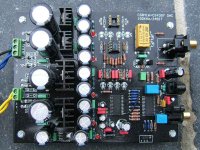
It's the big board DAC that I bought and modified, the one like here:
http://lampizator.eu/LAMPIZATOR/LAMPUCERA/MAX/maxi-lampucera.html
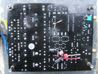
I added the resistors on the backside (more room).
But the biggest improvement soundwise was by changing the output stage to http://www.diyaudio.com/forums/show...?postid=1444038
Now I don't have any coupling caps after the cs4397, otherwise there were three stages coupled through caps.
Regards,
Danny
It's the big board DAC that I bought and modified, the one like here:
http://lampizator.eu/LAMPIZATOR/LAMPUCERA/MAX/maxi-lampucera.html
I added the resistors on the backside (more room).
But the biggest improvement soundwise was by changing the output stage to http://www.diyaudio.com/forums/show...?postid=1444038
Now I don't have any coupling caps after the cs4397, otherwise there were three stages coupled through caps.
Regards,
Danny
Attachments
Thanks for the nice pictures Danny !
Btw. i have smaller version "lampuchera" .I am already stuck with free space on my pcb + all elements on pcb are surface mounted and because of that it is very tricky to mortise those resistors.
Also ,the given link for the output stage doesn't work 🙂
Btw. i have smaller version "lampuchera" .I am already stuck with free space on my pcb + all elements on pcb are surface mounted and because of that it is very tricky to mortise those resistors.
Also ,the given link for the output stage doesn't work 🙂
Hello Chakija,
Here's the correct link for the output stage:
http://www.diyaudio.com/forums/showthread.php?postid=1444038
Yes, the bigger version has more modding space 🙂
I had the most problems with removing the obsolete parts and getting the holes free of solder.
It worked best with putting a steel needle on one side of the soldered hole and my solder iron on the other side, then the needle would go through, clearing the hole without getting stuck in the solder.
Regards,
Danny
Big CS4397 DAC mod
Hey Danny,
Can you please tell me what value caps and resistors you used for your output mod for the Chinese DAC; I have the exact same model and need help with doing the mods that you noted:
"I added the resistors on the backside (more room).
But the biggest improvement soundwise was by changing the output stage to http://www.diyaudio.com/forums/show...?postid=1444038
Now I don't have any coupling caps after the cs4397, otherwise there were three stages coupled through caps."
Looking at the picture you posted of the underside of the board; see the 220uf caps bypassed with small (value?) caps.
There are also a pair of RN55c (?) resistors .
Assume the bypass cap on the SPDIF in is a small .01 poly cap.
What is the other small tantalum cap value next to that.
Would appreciate if you can PM me with instructions if you have the time.
Sorry for bringing this old post up again.
Cheers all.
Big CS4397 mods
Anyone else here has done mods to this DAC.
It's the big CS4397 DAC that has the power supply and DAC circuit on one big board, and uses two transformers.
I enjoyed doing the mods to the small CS4397, and would like to try my hand at this unit.
Am looking for help on how to do the following mods to this big board DAC:
1k resistor mod to CS4397
DAC output resistors and bypass output caps
eliminate 2nd opamp circuit
Could find a ton of information on DIY mods for the small DAC board, but there is hardly anything on this big board DAC.
Any advice would be much appreciated.
Cheers.
Hello,
those decoupling caps are soldered directly at the V+, V- and GND pins of the opamp.
The two dale resistors are for the 1k mod of the CS4397.
Changing the output stage takes some work: you have to rip out a lot of caps and resistors and put the new circuit in.
Send me your mail address and I'll send you a high resolution picture of the topside so you can see how I did it.
Regards,
Danny
danny_66
Danny,
Here is my email; bighorn331@hotmail.com
Thank you for your assistance with this.
Hafp
Danny,
Here is my email; bighorn331@hotmail.com
Thank you for your assistance with this.
Hafp
- Status
- Not open for further replies.
- Home
- Source & Line
- Digital Line Level
- CS4397 CMOUT 2x1k mod