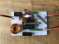
I'm in the process of building a small budget speaker using Dayton drivers, the TCP115-4 and ND25FA-4. I measured my drivers' raw responses and modelled my crossover using these measurements. I built the crossovers, but there seems so be something wrong.
The bass driver is almost completely silent. At first I thought it didn't do anything. The tweeter does make sound, but not very loud, and the TPA3116 amp switches of momentarily if I crank the volume up to about halfway (seems some built in protection).
Things I already checked:
I don't understand what's going on here. In the simulation software everything seems fine (though the impedance is quite low). Could anyone review my crossover and check it for errors?
The bass driver is almost completely silent. At first I thought it didn't do anything. The tweeter does make sound, but not very loud, and the TPA3116 amp switches of momentarily if I crank the volume up to about halfway (seems some built in protection).
Things I already checked:
- Checked my circuit layout at least 5 times
- Checked with another amp (TDA7498E), same result
- Disconnected the zobel network, no effect
- Disconnected the notch network, no effect
I don't understand what's going on here. In the simulation software everything seems fine (though the impedance is quite low). Could anyone review my crossover and check it for errors?
Attachments
It's possible that 56uF cap is shunting off most of your midrange, but it looks like polarized electrolytic as well. This the wrong kind of cap if it is, and needs to be nonpolarized. A zobel as normally used is not bigger than 20uF on a smaller driver, so this also seems really big.
Have you tried reversing the tweeter polarity to see if the summation isn't just out of phase and making a null at the xover?
Have you probed for VAC and have voltage at the woofer connection points? If you don't have voltage there, i would check the lowpass coil and make sure you have continuity between it and the board. Sometimes the varnish is not removed enough for contact.
Since you have low output on the tweeter too, i would ohm/continuity check all of your solder junctions and verify 0 where it should be 0.
Wolf
Hmm, just looked at the dxo in Xsim and it does seem as though it should work. Maybe a short somewhere.
A variable frequency impedance meter would be useful as you wondered yourself, if the impedance is too low for the amp.
Have you made a pair of these crossovers ..and is the other having the same problem? That would at least indicate whether its a solder or component fault rather than impedance\design fault.
Last edited:
Definitely disconnect the electrolytic and try the crossover. Reverse biased electros can short circuit; this one will be reverse biased half of the time. Replace with a bipolar as above.
Oops, The Mundorf is bipolar. I was foiled (pun intended) by the can being only crimped at one end, most bipolars have the can crimped at both ends.
Last edited:
What is the resistance of the crossover input measured with a multimeter? It should be open circuit with the bass driver disconnected, and the resistance of the bass driver added to the resistance of the 0.56mH coil when the bass driver is connected, i.e. around 4Ω. The crossover input resistance should not change whether the tweeter is connected or not in either case.
From you description of symptoms and the amp shutting down as you increase the volume it sounds to me like an almost complete short circuit on the input side of the crossover, like a single loose strand of copper in the input cable. I can't see one in the picture, but what about the other end not photographed - how is that terminated?
From you description of symptoms and the amp shutting down as you increase the volume it sounds to me like an almost complete short circuit on the input side of the crossover, like a single loose strand of copper in the input cable. I can't see one in the picture, but what about the other end not photographed - how is that terminated?
Last edited:
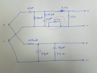
I don't think its the 4.7Ohm resistor (nice one for spotting the issue in that area though Tauntran) but the link back to the 2nd order inductor shouldn't be there? ...see attached file

Last edited:
Couldn't see why that would cause your issue but then added that link into xsim and noticed it drops the impedance above 15kHz down below 2 Ohms which the amps could be unhappy about?
If the crossover is actually built as the schematic shows the 4.7R isn't an issue, it's shorted out.Please check the 4.7 Ohm resistor.
First of all, thanks a bunch for taking the time to help me with this!
The 4.7Ω resistor isn't shorted out, even though it seems it is on the photo. The bottom wire of the parallel coil in the highpass section connects to ground. This coil is drawn somewhat diagonal, but in reality it's placed vertically and the bottom wire connects to the same pad as the left wire of the 4.7Ω resistor. This pad had been dremel'd (hard to see), so that this wire of the resistor is disconnected from the ground.
Also, the 56uF cap in the zobel network is a Mundorf ECap RAW capacitor, which should be bipolar. The values for the zobel network ware calculated using the information provided in this article (Re=3.2Ω and Le=0.97mH).
The wires leading to and from the crossover have XT60 connectors on them, for quick and easy testing. I'm pretty sure they don't short out, but I'll check to make sure, and will also measure the resistance of the crossover as per johnmath's suggestion.
Also, it's most likely not one faulty component, as I made two identical crossovers, both having the same issue.
I regret that I didn't first make a temporarily crossover before glueing it to the board and cutting all the wires, but lessons were learned.
Maybe the pad is dremel'd, but the black wire seems to connect (unintentionally) both part of the pad, causing the issue (impedance under 1 Ohm just before 20 KHz). To check if this is the problem, unsold one leg of your choice of the coil or cap of the notch (0.05 mH, 2.2 uF).
Ralf
The crossover has space for improvement, a 2KHz crossover is not really suitable to the tweeter
Ralf
The crossover has space for improvement, a 2KHz crossover is not really suitable to the tweeter
Will do.Maybe the pad is dremel'd, but the black wire seems to connect (unintentionally) both part of the pad, causing the issue (impedance under 1 Ohm just before 20 KHz). To check if this is the problem, unsold one leg of your choice of the coil or cap of the notch (0.05 mH, 2.2 uF).
You're absolutely right. This comes as somewhat of a surprise to me, I thought the XO point was around 3k. At 2k the tweeter will probably have considerably higher distortion and limited power handling. Knowing this, I might end up redesigning them altogether.The crossover has space for improvement, a 2KHz crossover is not really suitable to the tweeter
I think I'll disassemble one of the crossovers and rebuild them on a bench step by step to identify the issue. Even if I end up not using them, I still do to know what caused the issues.
Is the woofer itself working properly at all ? And is it properly connected ? Keep in mind that crossovers without drivers connected present a nasty load to a driving amplifier.
Regards
Charles
Regards
Charles
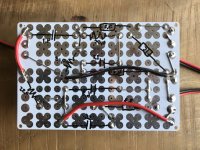
I think you are using the PCB wrong the single solder pads are actually connected together and covered by the white stuff. Therefore you are shorting some of your components, the two inner caps I think. See the Sound Imports picture.
Attachments
Is the woofer itself working properly at all ? And is it properly connected ? Keep in mind that crossovers without drivers connected present a nasty load to a driving amplifier.
The woofer works fine when connected directly to the amp.
I think you are using the PCB wrong the single solder pads are actually connected together and covered by the white stuff. Therefore you are shorting some of your components, the two inner caps I think. See the Sound Imports picture.
My goodness! I wasn't aware of that! That most likely explains all my issues.
- Home
- Loudspeakers
- Multi-Way
- Crossover acting weird, please help