Hi,
I’m hoping someone may be able to correctly identify the pictured transformer.
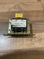
It’s fitted to a 20 year old Croft Vitale valve preamplifier which is showing short circuit across one of the secondaries and blows the 500ma internal fuse.
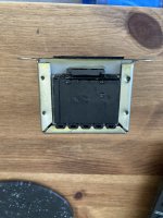
The part number shown on the front returns zero in Google search and unfortunately the genius and ever helpful Glenn Croft is no longer with us. The closest in size and value I’m able to find is a vintage RS components 207-144 available on EBay for around £20. Would this be a suitable replacement ?
Any advice gratefully received.
David.
I’m hoping someone may be able to correctly identify the pictured transformer.
It’s fitted to a 20 year old Croft Vitale valve preamplifier which is showing short circuit across one of the secondaries and blows the 500ma internal fuse.
The part number shown on the front returns zero in Google search and unfortunately the genius and ever helpful Glenn Croft is no longer with us. The closest in size and value I’m able to find is a vintage RS components 207-144 available on EBay for around £20. Would this be a suitable replacement ?
Any advice gratefully received.
David.
Attachments
First of all try to de solder the secondary connections so you can see if the fuse blown again ( internal short of trafo)
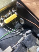
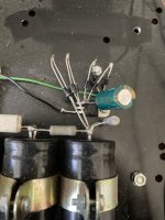
Check the yellow cap on primary
One of the secondary is filaments
I see a ic regulator (maybe)
7806 or 7812?
Maybe short
Send info in case
If the trafo is in short you need a filament secondary of 10 volt 1-1,5 A ( 7806) or 15 volt (7812)
For tube HT I think that 220-240 100mA volt can be reasonable
Which tubes are ?
Walter
Hi Walter,
Thanks for your suggestions.
With both secondaries disconnected the internal fuse blows. I already changed the 7812 regulator and 2200uf cap before finding that the filament secondary is shorted internally.
The amp uses an ecc82 for line amplification and a pair of ecc83 for the phonostage.
The transformer seems to resemble the older RS models circa 2000 and ideally a drop in replacement would be better.
David.
I'm not saying this one is the correct replacement https://uk.rs-online.com/web/p/chassis-mounting-transformers/0504662 but it does seem to have the same size label that has been removed from yours. Do you have a photo of the reverse side of your transformer?
Thanks for the link to the similar transformer from RS, I’ll spend some time researching the 504 series today.
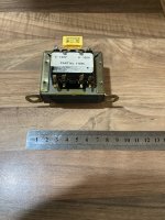
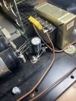
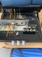
I’ve added further pictures of the tx reverse and Vitale internals. The voltage regulator is a L7812 and the cap is a 2200uf 25v which suggests the 2 secondaries are less than 24v. The known output is the main issue.
Does anyone own a similar Vitale or know the voltage required ? There is no information on line or even a circuit diagram to refer to.
David.
ps just weighed my tx at 431g while the 504-662 data sheet shows that at 550g but it’s very close in dimensions. I’m guessing my tx is possibly around 15 to 18v but obviously without a known circuit voltage it’s impossible to match a new one.
Why oh why was the original label removed on my tx 🤬
Attachments
I suggest to find a little bigger trafo
Probably with 2200uF the current capability of the filament sec was not enough during the inrush current
The voltage I wrote can be fine
Walter
Probably with 2200uF the current capability of the filament sec was not enough during the inrush current
The voltage I wrote can be fine
Walter
After further research the tx matches the dimensions and weight of RS 504 - 741, 751, 606, 599 & 616 which are 12, 15, 18, 20 & 24v respectively. Any of these will be an identical physical fit to the Vitale.
But which output voltage on the secondaries is the issue, although looking at circuit diagrams for the earlier Micro models on which the Vitale is based they use 12v outputs and as the 7812 voltage regulator will work correctly at this voltage I’m inclined to the 504-741 which is listed at 13.6v with no load ?
Any thoughts ?
David.
Sorry Walter just found your reply. So 504-751 at 15v (17.2 no load) would be more suitable ?
Although in your earlier reply it was suggested 230v for the ht supply whereas the 504-751 is 15v on both secondaries ?
Although in your earlier reply it was suggested 230v for the ht supply whereas the 504-751 is 15v on both secondaries ?
Perhaps there is no ht supply as such - the experts on here will be able to say what voltage the valves (ecc82/83) should be operating at.
Sorry Walter just found your reply. So 504-751 at 15v (17.2 no load) would be more suitable ?
Although in your earlier reply it was suggested 230v for the ht supply whereas the 504-751 is 15v on both secondaries ?
The 15 vac 1-1,5 A is fine for filaments
But you need to have also a HT voltage. Maybe a solution is a 220 vac primary and 220 vac secondary or 115+115 vac
Probably more easy to find
So are two trafos
Or to check on Hammond transformer site
Indeed. Looking again at the two bridge rectifiers, it maybe the one secondary feeding the regulator is for the (12Vdc?) heaters, and the other is to supply B+, but at what voltage? That is the question.
Last edited:
If one secondary is supplying the 12v for the heaters (13•6v without load) via the 7812 regulator that seems correct, but in all this type of tx both secondaries are the same voltage so surely the other secondary would be correct too ? I understand toroidal txs can have 2 or more different voltage outputs but don’t see this applying to my faulty tx type.
If the “ht” circuit required 230v why run it through a tx and not simply direct mains ac to the bridge rectifier ? Also the internal wiring to the bank of 4 220uf caps doesn’t appear too heavy gauge and the Vitale is only a preamplifier supplying small signal levels unlike a valve power amp which requires considerably more power to drive it.
I’m very tempted to try a 504-741 12v tx from RS which is an exact physical fit.
David.
This is a great error!!the “ht” circuit required 230v why run it through a tx and not simply direct mains ac to the bridge rectifier ?
Walter
What voltage rating are the bank of four capacitors, as that will give us a clue to what the secondary voltage should be?
Found this link http://www.cma4ch.org/chemo/attivita/croftsmic.html. Not the same model as yours but may give further clues on voltages and component matches, particularly if the voltage of the bank of capacitors corresponds.
Good idea Logic I’ll check after work.
Walter can you explain the great error
You can’t put the metal chassis at ground
There isn’ isolation from mains
Can be lethal
This was an old method for tube radio but the metal chassis was totally isolated from external contacts ( there were label well written)
- Home
- Amplifiers
- Tubes / Valves
- Croft Vitale transformer identification