Critique my SSR soft start circuit plz
I'm looking to switch AC mains using 2 SSR relays and a 3v3 signal from a raspberry pi with the following attached scheme.. I'm hoping to get an instant-on in the first relay, and a delay at the second, with both relays instant off.
Any special considerations involved in SSRs?
Muchas gracias

I'm looking to switch AC mains using 2 SSR relays and a 3v3 signal from a raspberry pi with the following attached scheme.. I'm hoping to get an instant-on in the first relay, and a delay at the second, with both relays instant off.
Any special considerations involved in SSRs?
Muchas gracias
I am not sure I read your circuit correctly, but are you intending to use SSRs for both relays?
If so, I would recommend to use a mechanical relay for the second one.
The reason is that an SSR always has some threshold voltage loss at zero crossing. This distorts the mains and may lead to harmonics and switching artifacts on the line that may end up in your system.
This is not an issue for the initial switch on, but for the second relay you can use a mechanical relay that does not have this threshold loss. Since this relay only has to switch the low SSR threshold plus whatever (small) voltage sits across the R, it only needs to be rated for the operating current of your load (transformer?) and not the full mains voltage.
You then should set up the on/off command so that at switch-off, you use the inverse procedure: you first close the SSR, then release the relay, then release the SSR. Piece of cake with a Rpi.
Jan
Last edited:
There will be no enough vbe voltage to open the second transistor. The voltage after Rr1 will never rise above about 0,7V. Hence it will be insufficient to open the serial connection of diode and the base of second transistor.
😱
Thanks Jan
So optotriac noisy?
How about a DIY MOSFET relay?
I have this desire to have no moving parts, although if absolutely necessary.. I just use as quiet operating as possible.
"There will be no enough vbe voltage to open the second transistor"
Thanks Chip
It had trouble under simulation as well, I used 100k Rr3 to ground resistor for it to work. I hadn't had the opportunity to calculate the exact values as yet. Looks like it won't actually turn out this way as it is.
How about an opto-driver and a couple N-MOSFETS?
Thanks
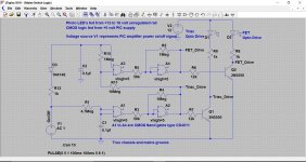
I've done some work on soft start circuitry using an SSR and triac that also does not include thermal time constants from thermistors. Prototypes worked reliably.
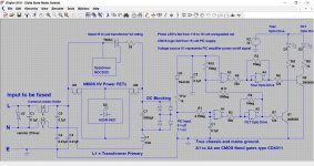
The logic circuitry is simple and connects the transformer initially via a triac, then after a short delay an SSR (a discrete SSR using power FET's and photovoltaic coupler) takes over placing a short across the triac.
Having no thermal time constants means the circuit can react rapidly to on/off cycling.
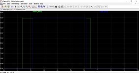
The time constant as shown are exaggerated, the SSR would activate after only a few 10's to 100's of milliseconds to suit the load.
The logic circuitry is simple and connects the transformer initially via a triac, then after a short delay an SSR (a discrete SSR using power FET's and photovoltaic coupler) takes over placing a short across the triac.
Having no thermal time constants means the circuit can react rapidly to on/off cycling.
The time constant as shown are exaggerated, the SSR would activate after only a few 10's to 100's of milliseconds to suit the load.
Attachments
Thanks ppl
I like the idea of discreet mosrelay.
Switching 500va total. Also considering switching both primaries individually as soft start.
Pondering...
I like the idea of discreet mosrelay.
Switching 500va total. Also considering switching both primaries individually as soft start.
Pondering...
Hi,
I design and built one that allow you to ramp the input AC on power ON/Off using a SSR no zero crossing relay that I used in my LM3886 amplifier built. It also minimizes the inrush current. It was built using the ZBASIC micro but I converted it to run on an Ardino UNO board. You are welcome to try it. I can provide you the sketch and the drawing. It is a simple design and it worked very good in my amplifier for almost 5 years with not problem.
I design and built one that allow you to ramp the input AC on power ON/Off using a SSR no zero crossing relay that I used in my LM3886 amplifier built. It also minimizes the inrush current. It was built using the ZBASIC micro but I converted it to run on an Ardino UNO board. You are welcome to try it. I can provide you the sketch and the drawing. It is a simple design and it worked very good in my amplifier for almost 5 years with not problem.
Thanks tauro
Feel free to share
At this point, it's looking towards what you have used, and similar to mooly, although I can see possibly two nfet switches perhaps. Switching both transformer primaries separate, or a thermistor possibly.
Do share
Thanks
Scott
Feel free to share
At this point, it's looking towards what you have used, and similar to mooly, although I can see possibly two nfet switches perhaps. Switching both transformer primaries separate, or a thermistor possibly.
Do share
Thanks
Scott
Hi,
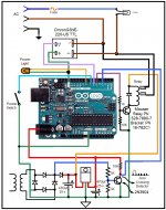
Attached are the Arduino sketch and the wiring picture to do the AC power control system using an Arduino UNO board.. It will slowly rampup/down the AC on power ON/OFF. To make sure it is working right after assembly try it to turn on a lamp. Wired the output from the solid state relay to an AC outlet and connect a lamp. You will see the light will slowly increase the intensity of the light same as when power down. later a will take a picture of my rig so you can see the above explained.
Attached are the Arduino sketch and the wiring picture to do the AC power control system using an Arduino UNO board.. It will slowly rampup/down the AC on power ON/OFF. To make sure it is working right after assembly try it to turn on a lamp. Wired the output from the solid state relay to an AC outlet and connect a lamp. You will see the light will slowly increase the intensity of the light same as when power down. later a will take a picture of my rig so you can see the above explained.
Attachments
You will see the light will slowly increase the intensity of the light same as when power down.
Like a pulsing LED when a system is asleep, only using 110v!
I think the only thing is that triacs are potentially noisy using that SSR.
I am looking around to see if I can put something together using MOSFETS. It would be nice to even have them switched slowly in order to simulate soft-start. There's so many different drivers and topologys that I have little idea where to start looking. I'm looking though. !!
Fun fun
Scott
Hi,
I am using the triac only in the ramp up/down then bypass the triac with a relay. The reason it wil keep firing on/off at the zero crossing to minimize the noise like you already point it out. It is a simple control system if you want to raise the voltage slowly up. This will will allow you to slowly charges the capacitors if you have a large bank of them. Also there it is not heat like when you use thermistor.
I am using the triac only in the ramp up/down then bypass the triac with a relay. The reason it wil keep firing on/off at the zero crossing to minimize the noise like you already point it out. It is a simple control system if you want to raise the voltage slowly up. This will will allow you to slowly charges the capacitors if you have a large bank of them. Also there it is not heat like when you use thermistor.
- Status
- Not open for further replies.
- Home
- Amplifiers
- Power Supplies
- Critique my SSR soft start circuit