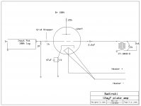
Please critique my schematic for a 12ay7 grounded cathode linestage using this trafo: http://jensentransformers.com/datashts/10kbd.pdf
I'd appreciate any feedback people may have. The trafo seems well-suited due to its high input impedance but modest ratio, so I keep a tiny amount of gain. Being an input transformer by nature, it wouldn't like DC so it's cap-coupled.
I'd appreciate any feedback people may have. The trafo seems well-suited due to its high input impedance but modest ratio, so I keep a tiny amount of gain. Being an input transformer by nature, it wouldn't like DC so it's cap-coupled.
Attachments
Last edited:
I built a line stage using the 12AY7 tube, but with a cathode follower rather than transformer coupled. I found that 280V B+, with 100K plate rsistor and 1.8K for the cathode resistor (with 470 mfd cathode bypass) worked very well for the gain stage. Given the palte resisitance of the 12AY7, you probably want more B+ and more plate resitance for lowest distortion and greater swing.
Your drawing has an inadvertent error--the output is shown coming off the grid rather than the plate.
Your drawing has an inadvertent error--the output is shown coming off the grid rather than the plate.
I built a line stage using the 12AY7 tube, but with a cathode follower rather than transformer coupled. I found that 280V B+, with 100K plate rsistor and 1.8K for the cathode resistor (with 470 mfd cathode bypass) worked very well for the gain stage. Given the palte resisitance of the 12AY7, you probably want more B+ and more plate resitance for lowest distortion and greater swing.
Your drawing has an inadvertent error--the output is shown coming off the grid rather than the plate.
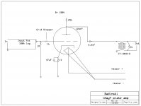
Thanks for the input! With the transformer, the lower output impedance of the lower plate resistor would not be the problem it is with the simple gain stage driving the output directly (as I'm using it now), so your suggestions make sense from that perspective. Attached is a corrected schema.
Attachments
Dude,
Look at the 12AY7 data sheet. RP is 25 KOhms. At least 3X the plate resistance, as the net load impedance, is necessary for low distortion. Your schematic shows a net load less than RP. 🙁
Replace that 25 KOhm part with a 10M45S CCS, if you don't want to increase the B+ rail voltage.
Look at the 12AY7 data sheet. RP is 25 KOhms. At least 3X the plate resistance, as the net load impedance, is necessary for low distortion. Your schematic shows a net load less than RP. 🙁
Replace that 25 KOhm part with a 10M45S CCS, if you don't want to increase the B+ rail voltage.
Dude,
Look at the 12AY7 data sheet. RP is 25 KOhms. At least 3X the plate resistance, as the net load impedance, is necessary for low distortion. Your schematic shows a net load less than RP. 🙁
Replace that 25 KOhm part with a 10M45S CCS, if you don't want to increase the B+ rail voltage.
Eli, you seem to be thinking the trafo is 1:1. It's not. It's 40k:2k4, which will load the tube with about 50k
Last edited:
Remember, that impedances in parallel follow a reciprocal law, to yield the net. As far as AC is concerned, the 25 KOhm resistor and the trafo are in parallel, hence the catch word parafeed. The net must be less than the smallest item in the parallel set. There's good reason why the parafeed circuits you see show either a huge inductance or a CCS as the connection to the PSU.
Eli, you seem to be thinking the trafo is 1:1. It's not. It's 40k:2k4, which will load the tube with about 50k
My mistake. NET load. I was ignoring the plate resistor. You guys can see why I'm needing the help, my tube chops aren't too impressive.
Yup, listen to Eli 🙂
I'm curious though, what is your signal source and what kind of peak swing can it deliver ?
Have you considered turning things around, i.e. your transformer at the input, reversed (for voltage gain), and tube wired as cathode follower ?
I'm curious though, what is your signal source and what kind of peak swing can it deliver ?
Have you considered turning things around, i.e. your transformer at the input, reversed (for voltage gain), and tube wired as cathode follower ?
I built a line stage using the 12AY7 tube, but with a cathode follower rather than transformer coupled. I found that 280V B+, with 100K plate rsistor and 1.8K for the cathode resistor (with 470 mfd cathode bypass) worked very well for the gain stage. Given the palte resisitance of the 12AY7, you probably want more B+ and more plate resitance for lowest distortion and greater swing.
Your drawing has an inadvertent error--the output is shown coming off the grid rather than the plate.
is there a chance that you post a schematic of your application ??? i have so many original motorola 12AY7 and i constructed afew things with them but i was never very happy with them
kind regards sakis
Hi Guys, Muffley:
280V and 100k do seem like more optimal operational points, though I'll probably juice up the cathode resistor a little higher, maybe 2.5k. Annoyingly, I'll have to change from a 6x4 fullwave to a solid state bridge to get the voltage needed. C'est La Vie.
After this, I'll still have a lower load on the tube, 2x Rp, but that's a heckuva improvement.
Hi Guys, Muffley:
280V and 100k do seem like more optimal operational points, though I'll probably juice up the cathode resistor a little higher, maybe 2.5k. Annoyingly, I'll have to change from a 6x4 fullwave to a solid state bridge to get the voltage needed. C'est La Vie.
After this, I'll still have a lower load on the tube, 2x Rp, but that's a heckuva improvement.
The 12AY7A isn't such a great choice for this application as you are finding. (rp a bit on the high side) You might consider Eli's suggestion of a CCS, or you might consider changing to a tube with a lower rp which would allow you to get away with a smaller plate load resistor. Were it me I would start over with a more suitable tube and the CCS..
The 12AY7A isn't such a great choice for this application as you are finding. (rp a bit on the high side) You might consider Eli's suggestion of a CCS, or you might consider changing to a tube with a lower rp which would allow you to get away with a smaller plate load resistor. Were it me I would start over with a more suitable tube and the CCS..
I have the CCS parts, so I may well toss one onboard and see what I come up with. I knew going in that Rp was much higher than normally seen, but I'm having a little fun playing around with this. Thanks for the feedback. My previous linestage was much less finnicky, a white cathode follower with 6922. That thing would have driven a mule.
Is it a "tubelizer", i.e. the device that adds specific tube distortions?
It's cool, if so. A tube choice, it's regime, all together solves this problem very well.
It's cool, if so. A tube choice, it's regime, all together solves this problem very well.
- Status
- Not open for further replies.
- Home
- Amplifiers
- Tubes / Valves
- Critique my schematic 12ay7 linestage