Hi all,
Attached is the schematic of my the Credo PMP154 (which I am repairing), that I traced and drew myself.
However there is one question, since I dont have much experience with solid state circuits, I am not sure about the function of the 4k7 trimmer near Q6 BC546. Can anyone help me?
Thanks
Attached is the schematic of my the Credo PMP154 (which I am repairing), that I traced and drew myself.
However there is one question, since I dont have much experience with solid state circuits, I am not sure about the function of the 4k7 trimmer near Q6 BC546. Can anyone help me?
Thanks
Attachments
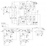
As it controls the bias current to only one side of the mirror image input stage, the trimpot can only be to null the DC offset at the output. The series-shunt resistors there are most likely to ensure safety, should the pot fail.
Hello,
I'm having issue with this amp again.
One channel had severe fault and I had to replace all transistors but for now it's not working.
At first it seemed fine when just Q1-Q6, their associated components and B++/B-- (+/-60VDC) are installed, I could get approx. 1mA through each pair of LTP.
But when I install Q7-Q10 the upper 3.9V zener couldn't hold its voltage, the drop on it decreased to about 1.3V. Now I have almost B++ at gates of Q11-Q14.
What could possibly went wrong?
Check for Q7 C-E short and measure B-E diode voltage. I suspect Q7 and Q10 are too fragile there or any parts may be below specification, depending on the actual source.
Q7-Q10 and the 2 3.9V zeners seems okay, I've checked them several time.
Here below are reading on the transistors (1-2-3 or CBE)
1. before installing Q7-Q10:
Q1: 57.77V/-40mV/-631mV
Q2: 60.00V/-125mV/-693mV
Q3: -59.13V/-40mV/497mV
Q4: -60.00V/-125mV/-715mV
Q5: 530mV/-56.38mV/530mV
Q6: -715mV/-54.63V/-57V
2. after installing Q7-Q10:
Q1: 58.70V/-50.8mV/-644mV
Q2: 60.00V/-195mV/-736mV
Q3: -60.00V/-50.8mV/386mV
Q4: -60.00V/-195mV/356mV
Q5: 386mV/58.60V/59.21V
Q6: -743mV/-56.43V/-57.03V
Q7: 59.37V/58.70V/59.42V
Q8: 59.36V/58.67V/59.37V
Q9: 59.1V/-56.48V/-44.69V
Q10: -44.69V/-60.0V-60.0V
Last edited:
- Home
- Amplifiers
- Solid State
- Credo PMP154 question