Hello Folks,
I'm attempting to building up a well done Power Supply for my Active 4-Way Speaker. Initially this looked simple 😉: Capable 750VA Transformer, Bridge Rectifier, 10000µF Capacitor, "here we go!". In the mean time I have learned and am implementing several things from this forum, incl. Snubbers, active rectification and now a CRC Supply.
Wanting to implement a CRC Supply for the 4-Way Active Speaker, I'm struggling with the proper dimensioning of the "RC"-part...😱

In principle I want to give each of the four Amps its own "RC", thinking that "sufficient locally buffered energy reserve (somewhat decoupled from the other amps)" must be a good thing. But I'm struggling with the size of Rs and Cs involved and ask the experts for helping advice, to learn this.
Thank you!
Winfried
I'm attempting to building up a well done Power Supply for my Active 4-Way Speaker. Initially this looked simple 😉: Capable 750VA Transformer, Bridge Rectifier, 10000µF Capacitor, "here we go!". In the mean time I have learned and am implementing several things from this forum, incl. Snubbers, active rectification and now a CRC Supply.
Wanting to implement a CRC Supply for the 4-Way Active Speaker, I'm struggling with the proper dimensioning of the "RC"-part...😱
In principle I want to give each of the four Amps its own "RC", thinking that "sufficient locally buffered energy reserve (somewhat decoupled from the other amps)" must be a good thing. But I'm struggling with the size of Rs and Cs involved and ask the experts for helping advice, to learn this.
Thank you!
Winfried
Attachments
I usually think about how much power I want do dissipate on R (to it wan't be too hot because it lower the capacitors life).
For power stage supply CRC I usually use a value not larger then 0.5-1.5 W dissipated (it depends on size of all system).
For one only amp it is optimal to use the same C as C1 and C2. For your case (several amps) C2 can be lower a little then C1. I mean in your case I'll use about 4700 uF for C2 (as start point).
As for me it doesn't seems to me to be easy to have low-noise system with one supply and several amps becase of groud will be a larger antenna. I mean I prefer to use one supply for one amp or one supply for two amps. But maybe it's just my inexperience. But if amps are phisically small (and close to each other) then everything is easy and no problem.
Last edited:
Lets take 0.5W dissipated at R, and 4A load current. That leads to too small R value (less then 0.1R) so to low RC-filter efficiency.
Lets use 0.1R. Then 4×4×0.1 = 1.6 W. Ok. I use 2x2W resistors in parallel or one 5W rated resistor (or even 2x 5W to they be cool if there is enough space).
If we use 4700 uF C2 caps then filter cut-off frequency is 1/(2×Pi×R×C), so f = 1/(2×3.14×0.1×0.0047) = 339 Hz (not as good as we want but ok).
If there is enough space (and money) then we can use 10 000 uF as C2 (or 2 x 4700 uF). That'll be fine. RC frequency will be about 159 Hz - that's good.
Last edited:
Why do you think 159hz is good?
Bigger caps are better, but it isn’t night and day difference between 4,700 and 10,000 uf
(the 2 x 4,700uf is better if you have room)
Bigger caps are better, but it isn’t night and day difference between 4,700 and 10,000 uf
(the 2 x 4,700uf is better if you have room)
Last edited:
It depends. It isn't "ultimate good". It is good enough for some case.
100 or 120 Hz is frequency of voltage pulsations.
In that case it is something like "cheap good", or "efficiency/money good". 🙂
Because filter will work ok in mid-audio frequency range (about 1 kHz and higher).
100 or 120 Hz is frequency of voltage pulsations.
In that case it is something like "cheap good", or "efficiency/money good". 🙂
Because filter will work ok in mid-audio frequency range (about 1 kHz and higher).
Last edited:
How about a 0.5 ohm resistor and a heck of a lot more capacitance? 🙂
ERSE Super Q 17mH 16 AWG 500W Inductor Crossover Coil
ERSE Super Q 17mH 16 AWG 500W Inductor Crossover Coil
By the way, the power draw for your 4 channels (using only one side for argument's sake) will be nowhere near equal. For most music, the 50/50 power split happens between 250-350 Hz, stretching higher with acoustic instrument-based music, and reaching lower with electronic/drum-heavy music. i.e. this is the point at which the power required for the lower part of the spectrum is the same as for the upper part.
BiAmp (Bi-Amplification - Not Quite Magic, But Close) - Part 1
Your upper-most channel will require very little power, relatively speaking, so it doesn't make sense to be the same amount of power (or capacitance) as the other channels.
BiAmp (Bi-Amplification - Not Quite Magic, But Close) - Part 1
Your upper-most channel will require very little power, relatively speaking, so it doesn't make sense to be the same amount of power (or capacitance) as the other channels.
Lower power channels may have the same filter capacitance but larger RC-filter resistance (it is better then lesser the capacitance).
Last edited:
Why use the same amount of capacitance? The C is only there to reduce ripple when there is a current demand, and the lower the demand, the less C you need.Lower power channels may have the same filter capacitance but larger RC-filter resistance (it is better tben lesser the capacitance).
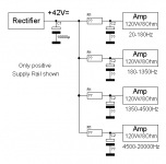
...Active 4-Way S...., 10000µF Capacitor, "here we go!". ....(only positive rail shown).....
I think 1,000uFd across both rails is Really Cheap. Like a $39 phonograph from 1971. For dual rails that is two 2,000uFd. For four channels dual rails this is two 8,000uFd. For "Really Cheap"!
And e-caps have got really cheap (low price). Why be stingy? Modern fashion would encourage two 10,000uFd *per channel*. While the tweet channels might use a bit less, some folks would use a lot more on the bass. So two 40,000u or eight 10,000u, before you even get to a "second filter".
The R-C filter is discussed in RDH where 20% drop is advised for low-level stages. Taking less drop in R will force much larger C for good filtering. Of course 20% drop to a Power stage makes 64% the power. And in an AB stage, on speech/music, major rail-thump. (IMHO this signal-varying supply makes R-C filtering a bad idea for AB amps.)
Finally: a well-designed modern power amp has excellent PSRR, at least in the lower audio frequencies. When I've had hum/buzz in a power amp, even some antiques, it has usually been poor wiring or grounding layout.
If each amp has good PSRR you don't need to worry about this, resistance will reduce headroom and is generally undesirable. If you have enough capacitance per amp to reduce mains ripple to a level that makes the outputs quiet at mains frequency, it will also work at higher frequencies.
Its more important to ensure the decoupling has low enough series inductance to cover the audio band at low impedance I think.
Theoretically a 10mF capacitor is 1.5 milliohms at 10kHz, so that 5A ripple shows as 7.5mV on the rail. With only 50dB PSRR that's 24µV disturbance to the other amps while the amp providing the 5A pulses is probably at 40V output levels, ie a ratio of 124dB. That's acceptable.
At lower frequencies the ripple will be larger, but amp's PSRR also increases at lower frequencies...
So think carefully about the impedance/frequency curve of the decoupling sections on each amp, paralleling lower value capacitors if necessary to make up for the series inductance of the main filter caps.
Hello Folks,
thanks for the enlighting and engaged discussion which gives me some good learnings! Your considerations seem worth more thoroughly digging into, as I understand that doing it "right" is not necessarily straight forward. So please consider the following:
1. The 2x 10mF was the original speaker design (by the manufaturer) for the power VFETs, I'm ready to "invest" more mF with the appropriate approach.
2. The 4 modules have a separate supply voltage of +/-42V for the VFET Power-Stages and +/-50V for the Gain/Driver-stage. These were designed in the early 90s.
3. I don't know the PSRR of the Power Modules. How would I measure this? (Equipment like Scope, LF mV-Meter and LF Generator are available).
4. One rationale behind additional RCing for each of the power modules had been to provide a local energy buffer for each (to somehow "decouple" supplies if this makes sense...?).
5. When I bought the speakers, each module had and still has a 2,200µF e-cap in their VFET Supply lines right next to the VFETs (in parallel to the 100nF in the original manufacturer drawing). I could increase these to 5...10mF each quite easily.
6. So far I did not "hear" hum from the modules, just a bit of hiss.
Maybe this helps to recommend how I could successfully proceed. The previously stated idea to use inductances to achieve better power supply quieting sounds like a good solution, but space is limitated and I'm unsure about magnetic fields generated near to the electronics (there are speaker sensor feedback-loops involved)...
Thanks again for helping!
Winfried
There is an easy way - just only put one powerful R in between thoose 10 mF and thats it.
Because it is designed yet (and I don't have device on my hands) I can't make exact valuable recommendations.
Just remember that you can't move caps from theirs places (if device PCB is fine designed). You can only add in parallel, or change to a larger ones only if there is enough free space near that caps.
Last edited:
Rather than measure PSRR, just drive one amp at full output into dummy load and monitor the leakage to the other amps (inputs shorted) for various power supply configurations, thus answering the question that's actually important to you.
Hi Mark,Rather than measure PSRR, just drive one amp at full output into dummy load and monitor the leakage to the other amps (inputs shorted) for various power supply configurations, thus answering the question that's actually important to you.
thanks for the great recommendation! Really seems a good way to reasonably ensure what I want to achieve. But I'm sorry, I don't know how to measure the leakage to other amps... 😱 I do have a dual trace Scope at hand, though.
Regards,
Winfried
Try measuring the output on those other channels.Hi Mark,
thanks for the great recommendation! Really seems a good way to reasonably ensure what I want to achieve. But I'm sorry, I don't know how to measure the leakage to other amps... 😱 I do have a dual trace Scope at hand, though.
Regards,
Winfried
> how to measure the leakage to other amps...
What do you realy want to know? How can you know it?
Drive one channel "LOUD" but in a dummy load. Connect speakers to the other channels. Do you hear anything? Would you hear that if the LOUD channel had a speaker?
If channel A can make 95dB loud and channel C leaks 20dB, it is very little leakage indeed.
Yes, you can do "better". It can be an endless bottomless pit chasing "isolation". Separate transformers. Separate house-circuits. Separate power Companies. (Transmitters, server farms, and other high-value systems do try to connect to two unrelated power companies.)
- Home
- Amplifiers
- Power Supplies
- CRC Supply "done right"