Hello everyone!
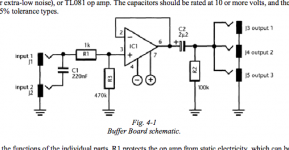
I have this buffer thingy that I made a long time ago in a neat little box. I was thinking that I could use it for the piezo pickup on my upright bass.
1. Will changing R3 to 1M make the input impedance 1M?
2. Can I make a simple first order high pass filter by changing the value of C2? I guess something between 50 to 100 Hz would help to reduce the unnecessary low end rumble. Can I count the cutoff frequency with this: f=1/(2*pi*R2*C2) ?
3. Can I make a polarity switch by installing a DPDT switch somewhere? What might be a good point for that? Is it really possible when the chassis is the ground?
Thanks!
Attachments
1. Will changing R3 to 1M make the input impedance 1M?
2. Can I make a simple first order high pass filter by changing the value of C2? I guess something between 50 to 100 Hz would help to reduce the unnecessary low end rumble. Can I count the cutoff frequency with this: f=1/(2*pi*R2*C2) ?
3. Can I make a polarity switch by installing a DPDT switch somewhere?
Yes and yes (if there isn't much loading at the output to change the roll off). But, more circuitry is needed to be able to select signal polarity.
Either a second, inverting stage to switch in and out, or else reworking the single stage as a switchable input diff amp type circuit.
Last edited:
Cool, thanks!
The input impedance on the next stage will be either 1M on the tuner or 500k on the amp. Maybe I should take that into account somehow?
The input impedance on the next stage will be either 1M on the tuner or 500k on the amp. Maybe I should take that into account somehow?
The input impedance on the next stage will be either 1M on the tuner or 500k on the amp. Maybe I should take that into account somehow?
Yes, just calculate that in parallel with all the other resistor(s) at the output. The frequency will vary if the total load resistance varies.
This buffer is working great! R3 is now about 1.7M because I happened to find a resistor of that value in my drawer. I added a 47n capacitor in series with C2 and it reduces the rumble just fine. Rehearsal is tomorrow and the gig on new years eve. That will be the real test.
I was thinking about the IC. It is a TL071 and it sounds just fine. Is there a more modern replacement that would sound better? The IC sits in a holder so it would be an easy swap. Or is just a waste of time? Actually I should be practicing right now!
I was thinking about the IC. It is a TL071 and it sounds just fine. Is there a more modern replacement that would sound better? The IC sits in a holder so it would be an easy swap. Or is just a waste of time? Actually I should be practicing right now!
The NE5534AP is not unity gain stable, it won't work in that circuit.
You would need to add external compensation to make it stable.
Mike
You would need to add external compensation to make it stable.
Mike
The NE5534AP is not unity gain stable, it won't work in that circuit.
You would need to add external compensation to make it stable.
Mike
In addition it doesn't have a high impedance fet-input like the TL071 and OPA134. So, I will try only the OPA134.
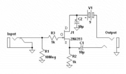
Back from the rehearsals. The bass sounded better than ever before through an amp. I was thinking that maybe I should try to make another buffer with a discrete FET. Like this one here by Scott Helmke:

Back from the rehearsals. The bass sounded better than ever before through an amp. I was thinking that maybe I should try to make
another buffer with a discrete FET.
Such high impedance levels will be prone to noise pickup. You can easily scale the impedance levels for everything on the input side
down by a factor of 10 or even 100. Make the resistors smaller, and the capacitors larger, by the same factors.
There should be a gate resistor on the fet.
Last edited:
Here is another one by Francis Deck. This one has the gate resistor. These extreme input impedances are thought to be "better" with piezo pickus.
The high pass filter is an essential component. I would need to add one.
A polarity reversal switch would be useful too to fight the feedback. A design of one still eludes me.
The high pass filter is an essential component. I would need to add one.
A polarity reversal switch would be useful too to fight the feedback. A design of one still eludes me.
Attachments
Last edited:
- Status
- Not open for further replies.
- Home
- Live Sound
- Instruments and Amps
- Craig Anderton Buffer Board mods