Hi,
Sorry if this is a very basic question. Still wrapping my head around the physics of horn design. Reading through the MJK notes, he mentions the coupling chamber, which if i'm guessing right is another name for a compression chamber?
In the notes he talks about the 'coupling chamber area at the closed end' & 'coupling chamber area at the open end'. what exactly is this referring to? The pictures given show that the coupling chamber is rectangular (I don't know if that's always the case). So is the closed end the short side, and the open end the long side?
Thanks
Normally, a horn "compression chamber" is sealed.Reading through the MJK notes, he mentions the coupling chamber, which if i'm guessing right is another name for a compression chamber?
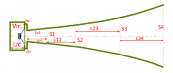
In the Hornresp simulations, a normal horn compression chamber is abbreviated as Vrc (Volume of Rear Chamber).

Using Hornresp, what you depict can be modeled as a "Back-Loaded Horn".

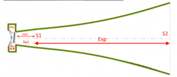
Vrc and/or Lrc (Length of Rear Chamber) are set to = 0, the "coupling chamber" as depicted would be specified as Vtc (Volume of Throat Chamber) and Atc (Area of Throat Chamber). Up to four horn sections can then be specified, S2,3 or 4 terminating at the mouth.
I have not seen the MJK notes, so can't help you there, but in Hornresp there are probably options to simulate whatever you may see there.In the notes he talks about the 'coupling chamber area at the closed end' & 'coupling chamber area at the open end'. what exactly is this referring to?
Ap1 Throat port or throat adapter entry cross-sectional area (sq cm).
Ap2 Throat port 2 or absorber chamber port cross-sectional area (sq cm).
Lp Throat or absorber chamber port or throat adapter length (cm).
Vtc Throat chamber volume (cc).
Atc Throat chamber average cross-sectional area normal to axis (sq cm).
The chamber (s) can be any shape or volume or length deemed appropriate, though the Hornresp model assumes them to be circular. The shape does not matter much for low frequency simulation.The pictures given show that the coupling chamber is rectangular (I don't know if that's always the case).
It could be ;^)So is the closed end the short side, and the open end the long side?
Harold Karlsson's Hornresp manual is a better help than I'll ever be:
https://www.diyaudio.com/community/threads/hornresp-manual.383370/#post-6951804
Greets!Reading through the MJK notes, he mentions the coupling chamber, which if i'm guessing right is another name for a compression chamber?
Technically it's an acoustic low pass filter. Haven't gotten familiar with the latest HR rev., but at a glance, not seeing a way to do offset driver variants of it, so (for now) means only Fig. 1 is the closest available and yes, offset drivers can make a worthwhile difference depending on the horn's design parameters.