I've found this interesting microphone preamp schematic on the web, but there's one thing confusing me - input coupling capacitors voltage rating:
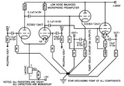
Why is it set to 415V, when those capacitors can't see more that 50? Am I safe to go with 63 or 100V rated capacitors (Wima MKP4) here?
Also, AFAIK, there's really no need to use 10uF capacitors if they're followed by 1M resistor to ground, because it creates high pass filter with 0.02Hz. Am I right if I think that input coupling caps can be reduced to 100n (giving 1.59Hz cut-off frequency). Does the same apply to output coupling caps, or we must take next unit's impedance into calculation?
Last edited:
The image is to small to make out but 415V 10uF electrolytics look wholly inappropriate as an input coupling cap. Your suggested 0.1uF should be fine.
You must take into account the impedance of the following stage when dealing with output coupling caps, and that will appear in parallel to the resistor already present on the diagram.
You must take into account the impedance of the following stage when dealing with output coupling caps, and that will appear in parallel to the resistor already present on the diagram.
Can't read it (too small) but think of this- What happens at warm up time, when the tubes are cold and essentially an open circuit? Rate them for the maximum DC voltage (plus a little headroom to account for an unloaded power supply or higher AC line voltage) that they are ever likely to see in the given circuit. Sometimes this isn't very high, sometimes it can be the full power supply voltage.
As for the size of them, you can safely make them much smaller- it's usually common practice to make them able to pass a decade or so lower in frequency than your desired lowest frequency. I routinely go for a 1M/100nF for the majority of builds unless I have compelling reasons to do otherwise, sometimes I go 33nF or 47nF with 1M if it's a lower power amplifier that isn't likely to need to reach very low.
As for the size of them, you can safely make them much smaller- it's usually common practice to make them able to pass a decade or so lower in frequency than your desired lowest frequency. I routinely go for a 1M/100nF for the majority of builds unless I have compelling reasons to do otherwise, sometimes I go 33nF or 47nF with 1M if it's a lower power amplifier that isn't likely to need to reach very low.
Oh, I see, this site doesn't handle postimg.cc's thumbnail links well. Here is full size image:

Last edited:
So if I have some kind of B+ delay circuit, I can go with lower voltage for input caps?Can't read it (too small) but think of this- What happens at warm up time, when the tubes are cold and essentially an open circuit? Rate them for the maximum DC voltage (plus a little headroom to account for an unloaded power supply or higher AC line voltage) that they are ever likely to see in the given circuit. Sometimes this isn't very high, sometimes it can be the full power supply voltage.
The input caps don't need to be 10u OR 415V as they will never see B+, only the phantom power. 0.1u/100V will be fine, and depending on what this amp will drive you won't need 10u output caps, either.
I'd try 2u2/400V on the output.
I'd try 2u2/400V on the output.
10uF and 1 Meg Ohm has a 10 second time constant.
In 50 seconds, the cap will be charged to 95% of its final voltage.
But wait . . .
in the case of 50V phantom power, in 10 seconds, the 12AX7 will already be warm, so the grid current will charge the cap in under the 50 seconds. But, do you want all that grid current (charge) from a large capacitance?
And, the 12AX7 cathodes are going to try and follow their grids, and will attempt to take the LM334Z to +50V at the beginning of the 10uF charge time
(and will do the same with 0.1uF, just for a shorter time).
LM334Z @ 50V!
Try it.
10uF and 1 Meg Ohm is -3dB @ 0.0159 Hz!
Overkill?
And that assumes that if an electrolytic is used (electrolytics should not be used to couple to grids), that there is no DC leakage of the electrolytic, or it will never settle to final full charge, it would be a resistive divider (100Meg leakage, and there will be 0.5V at the grid).
Where did the schematic Originally come from?
A Seismograph preamp?
I believe a 1 Meg resistor is not going to allow the best noise performance out of a 12AX7 at low frequencies.
But 1 Meg Ohm will allow us to see if there a gassy 12AX7, or if a proper .1 uF coupling capacitor is leaky (just look at the uV or mV across the 1 Meg Ohm).
And notice the 2.2k Ohm resistor from the phantom power supply. The microphone has to drive 2.2k Ohms in parallel with 1 Meg Ohm, 100 feet of microphone cable, and the 12AX7 miller capacitance (small compared to 100 feet of microphone cable).
Last edited:
Correction:
(* 30 *), not 50 seconds
(* 30 *), not 50 seconds
10uF and 1 Meg Ohm has a 10 second time constant.
In * 30 * seconds, the cap will be charged to 95% of its final voltage (still 2.5V on the 12AX7 grid).
But wait . . .
in the case of 50V phantom power, in 10 seconds, the 12AX7 will already be warm, so the grid current will charge the cap in under the * 30 * seconds. But, do you want all that grid current (charge) from a large capacitance?
Last edited:
Obviously this is a Wondercap design, to push sales of their products.
Serious schematics and definitely *all* equations do NOT include BRAND as a parameter, so any schematic specifying any can safely be considered Snake Oil.
Back to the Tech area:
* input caps can very well be the 100nF ones you calculated, which is a very sensible value.
* 10uF 415V , or even 1uF ones at the output are fine, your load is not the 1M ground reference shown there but "whatever lies at the other end of the cable" .
Even IF it´s, say, a 1M input impedance preamp, you want that generator low output impedance afforded by cathode followers to keep noise/interference low.
This is actually condenser mic pre, found it on a web site by the guy from Croatia. He claims that he designed this preamp for a famous Croatian rock band, Jinx.
Balanced tube microphone preamp
If I expect another pre or computer audio interface "at the other end of a cable", what is the reasonable output cap?
Also, I think that even if the tube is cold, grid can't see more than phantom voltage. If B+ leaking to grid in cold tube is possible, every guitarist plugged into a cold guitar amp will die after turning it on.
Well, it definitely can not drive a 600 ohm input, so it´s reasonable to expect a Mixer Line In or a power amp In,mid to high impedance, 1hink 10k and higher.
If 10k, a 10uF coupling cap there will match a 100nF one at the input so it´s a sensible choice.
Nice band, very Eastern European.
FWIW they seem to be using an old style *dynamic* microphone, not a condenser type one ... which would require a built-in preamp because of the huge impedances involved, so your schematic would hardly be driven straight by microphone electrostatic plates.
A Classic "Balanced In/Balanced Out" preamp would definitely have used transformer coupled input and output.
- Status
- Not open for further replies.
- Home
- Amplifiers
- Tubes / Valves
- coupling capacitors voltage