When designing a valve amp we have to calculate or choose a coupling cap value which with a grid leak resistor forms a high pass filter using the formula 1/(2 * pi * f * r) this gives us the 3dB roll off frequency of the RC filter. I usually choose a low frequency something like 7 - 15 hz. Traditionally the value of the coupling cap gets bigger the nearer to the OP stage, EG 10n/1M from V1 to the phase splitter & 220n/220k.
I've found I build the amp, test it on the bench, all tests ok then give it a listen but find that the LF response is too low or too high , not quite right in other words. So, is there a way, a method to calculate each coupling cap?
Andy.
I've found I build the amp, test it on the bench, all tests ok then give it a listen but find that the LF response is too low or too high , not quite right in other words. So, is there a way, a method to calculate each coupling cap?
Andy.
Have you tried designing all the coupling networks to be much lower in response, say below 2 Hz? If you cascade several stages with AC coupling then the overall effects, including phase shift, start working their way up into the audio band.
Yes, but often find when listening the bass is too much, or not subtle.Have you tried designing all the coupling networks to be much lower in response, say below 2 Hz?
Yep, each RC coupling cap combo forms a HPF rolling off LF by 3dB but the phase shift happens at much higher frequencies. Ultimately the LF response is dictated by the OPT, by it's primary Z, it's inductance, however what AC coupling you choose also effects the sound. EG the first stage cathode bypass cap, anode to following grid stages coupling cap, etc.If you cascade several stages with AC coupling then the overall effects, including phase shift, start working their way up into the audio band.
As each RC HPF rolls off the LF by 3dB one would think you'd use higher value coupling from IP to OP stage so that LF isn't attenuated too much,EG 1u, 100n, 10n but from vintage amp designs I've seen, the opposite is true, EG 1n ,10n, 100n. These being gross simplifications.
Obviously the elephant in the room is LF stabilty which also comes into play.
Last edited:
A good practice is to use 10x or even 20x lower LF rolloff in each stage except the last one. Also the LF rolloff of the output transformer should be 10x lower than the last coupling capacitor-grid leak resistor rolloff frequency. In summary, there should be one dominant pole in the chain. This is especially important if there is global negative feedback.

Could you expand on that please?A good practice is to use 10x or even 20x lower LF rolloff in each stage except the last one.
Is that the OP stage? Dominant in terms of LF or HF? Still a bit fuzzy about poles.In summary, there should be one dominant pole in the chain.
Could be either a SE amp with no NFB or a PP amp with NFB: either or.Does this amp incorporate feedback?
Thanks all, Andy.
Last edited:
The answer can be quite different depending on feedback or not. Most of the responses thus far have assumed no feedback.
In that case the overall high pass is just the dB sum of all the transfer function zeros. Haven't given much thought to the dominant zero location, but the OP transformer is one you are stuck with and can easily be engineered to be dominant.
In the case of feedback, the zeros (and low pass poles) get suppressed by the feedback loop gain in the closed loop response. Careful attention must be given to the overall loop stability at both low and high frequencies. In the case of low frequencies (high pass response governed by zero locations) phase can quickly accumulate with each zero in the loop, and lead to motor boating. The analysis is not simple as the transformer is not easily modeled in this region of operation.
In PP output stage a good output transformer will have plenty of inductance and the low frequency cut-off (-3dB) can easily be in the 2-3 Hz region...
Frequency response (1W) not to be confused with power response. I have never picked up a coupling cap with such roll-off requirement unless it's straightforward. I generally don't go beyond 1 uF (better if less) because that's normally where the loss rating of capacitors changes and gets worse. Very good capacitors (truly low loss) with more than 1 uF capacitance are fairly expensive-to-outrageously expensive....
Frequency response (1W) not to be confused with power response. I have never picked up a coupling cap with such roll-off requirement unless it's straightforward. I generally don't go beyond 1 uF (better if less) because that's normally where the loss rating of capacitors changes and gets worse. Very good capacitors (truly low loss) with more than 1 uF capacitance are fairly expensive-to-outrageously expensive....
Last edited:
To be honest the only stability issue's I've had were with a PPP EL34 120w amp, but that's a lot of power and gain. With SE amps I've found that they sound better with no FB, but they may test better with NFB.
With PP amps of 10w to 35w I've had no issue's with stability with 3 stages inside the FB loop. The tricky bit is getting the LF response just right so that it's not dominant & over whelming but not whimpy & flat.
Andy.
With PP amps of 10w to 35w I've had no issue's with stability with 3 stages inside the FB loop. The tricky bit is getting the LF response just right so that it's not dominant & over whelming but not whimpy & flat.
Andy.
A "dominant" pole is one that brute-force dominates all other poles, so they can be ignored. Like all modern feedback thinking the term comes from opamp theory. If you get interested in feedback, the place to start is learning basic opamps and Bode plots. These are just stick-figure simplified versions of frequency and phase response drawn together on a log-log chart, very easy and intuitive. Toob guys resist learning the fundamentals, but then they never understand. Gotta begin at the beginning.
In feedback amplifiers the dominant pole is best placed at the grids of the output valves, because that's where clipping occurs and recovery time from clipping (which is just overdriving the output valves' grids) varies inversely with that RC time constant. The output transformer's low frequency pole isn't safe to use as a dominant pole because it varies (a lot) with signal level, and changes go in the wrong direction for stability. These issues are true for long loop feedback, and for feedback taken from the OPT primary.
All good fortune,
Chris
Coupling cap choice
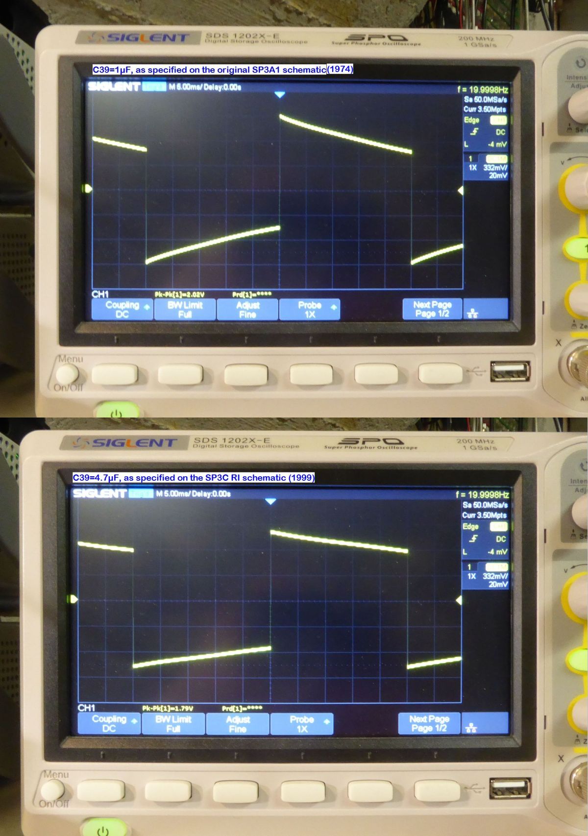
Even if Fc=1/2PiRC, the maximum µF is the best - assuming of course that the amp stability is not affected, or if you don't need to fight any rumble effect of some kind that would damage your speakers. A look to square waves will show you the benefits.As an example below, on an Audio Research SP3A1 preamplifer, at 20Hz, difference between 1µF and 4.7µF output capacitor :
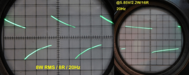
Below, the coupling caps from phase inverter to power stage on my U-OTL amp are increased from 1µF at left, to 10µF at right. Output waveform @20hz/8R :
T
Attachments
Last edited:
- Home
- Amplifiers
- Tubes / Valves
- Coupling cap choice