Hi,
After reading this, interesting thread on the Azure 540r, I have found one that I would be interested in buying, but by now, the quite many electrolytics are ripe for replacement anyway, and that would be a good time to rethink if any improvements would be a good idea.
The original thread mentions upgrading and even removing some of the caps in the signal path. As the originals are single (not back to back), polar electrolytics I am assuming that some dc offset is designed in and that removal is not an option (please correct me for the specific caps in question if I am wrong).
I am not an expert in circuit design, so if anyone has time to look at the original thread and give good advice, it would be much appreciated. Please feel free to comment on the op-amp rolling plan as well.
Many thanks!
Sounds and looks uncomfortably silly to short circuit the capacitors. A number of issues will arise; no/poor mute function and DC offset problems.
Replace the capacitors by all means for higher quality types but do not change the values!
OP Amps can be changed but I doubt any noticeable difference will be observed.
Replace the capacitors by all means for higher quality types but do not change the values!
OP Amps can be changed but I doubt any noticeable difference will be observed.
Thanks John!
Would BlackGates still be the best option there or are there newer, better sound for the buck alternatives. Am assuming that at 10u electros are my only real option, but would NP be a better choice?
Regarding op -amp rolling, the JRC2068's do have a bad press, but am always scheptical to instability and oscillation if changing without knowing that stability is taken care of.
Cheers!
Cheers!
How deep is your pocket is the answer. Personally, Sanyo, Philips and many Japanese manufacturers supply electrolytics of excellent quality at a keen price. Take a look at Mouser, RS, Farnell etc for some ideas. Black Gate I have never rated because they are in my opinion too over rated. The design of the Cambridge Amplifier takes into account the tollerances of the components used and probably will not improve with better quality Tant or Foil capacitors.
Perfect! Thanks! Pocket is sadly especially shallow at the moment after being ripped off by cowboy builder 😉 Hence the second-hand amp.
I'm attaching the schematic that was posted on the original thread.
Having looked a little closer I have to admit that I don't understand the function of all of the coupling electrolytics, so I hope someone here can help explain how this design works.
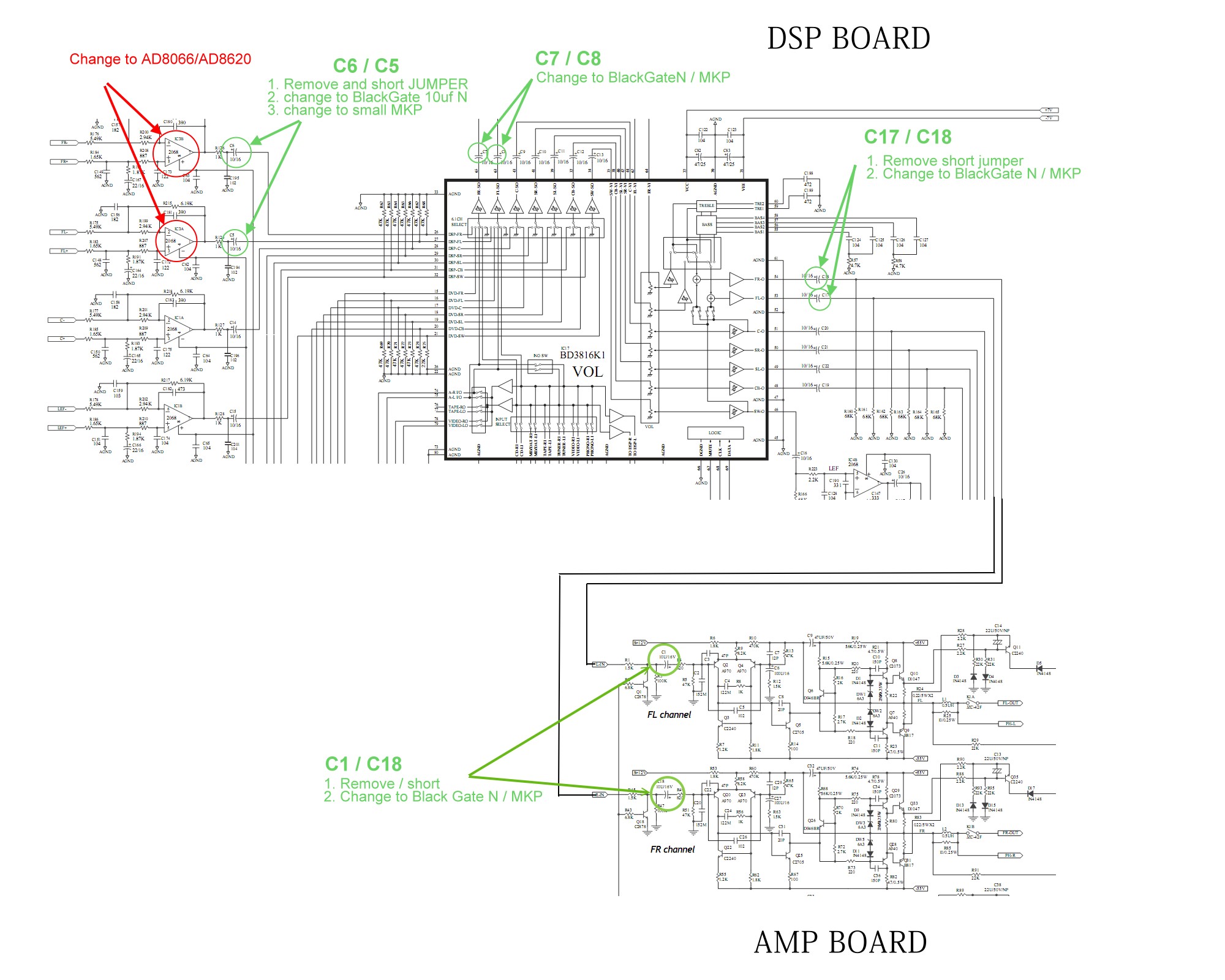
If we take the FR channel as an example, C6/C7 seem to form a back to back pair, with a trimpot in between. I also fail to see any new, DC injection danger before the power amp input at C18 (power amp). I am far from expert, but surely this is overkill. replacement of all of these with a single MKP looks as if it would do the same job from a coupling perspective. Why polar caps and why so many?
This schematic is lifted straight from the thread started in 2009 by sviru, so please disregard the suggestions in red and green, especially regarding op-amp rolling, where this article suggests that the NJM2068 may indeed be the very best choice there is in low gain input applications.
Having looked a little closer I have to admit that I don't understand the function of all of the coupling electrolytics, so I hope someone here can help explain how this design works.
If we take the FR channel as an example, C6/C7 seem to form a back to back pair, with a trimpot in between. I also fail to see any new, DC injection danger before the power amp input at C18 (power amp). I am far from expert, but surely this is overkill. replacement of all of these with a single MKP looks as if it would do the same job from a coupling perspective. Why polar caps and why so many?
This schematic is lifted straight from the thread started in 2009 by sviru, so please disregard the suggestions in red and green, especially regarding op-amp rolling, where this article suggests that the NJM2068 may indeed be the very best choice there is in low gain input applications.
Last edited:
coupling capacitors are usually inserted where an AC signal must pass, but where there is a difference in DC voltage on either side.
Coupling capacitors are DC blocking capacitors.
Almost all coupling capacitors act as filters with the resistance/impedance that is in circuit.
You can calculate pretty closely the roll off frequency of these filters and use the results to choose a new /replacement capacitor.
You may find that a plastic film capacitor can replace a cheap electrolytic and still fit the space allocated on the PCB.
Get your calculator out and find the roll-off frequencies.
Make informed decisions. Don't guess and don't just accept advice, check it. Check mine as well, does anyone agrre with me?
- Status
- Not open for further replies.
- Home
- Amplifiers
- Solid State
- Coupling cap advice : Cambridge Audio Azur 540r