i bought a counterpoint sa100 15 yrs ago. it was ok.until recently. i have 1 channel making a low frequency whoomp! now and again. i unplug it. wait a day, turn it on and it will work for a while.
i hope it is a capacitor because i plan on replacing the electrolytics on the board.
the transformer windings are 259v for the b+ and 34 0 34 for the output. the board is burnt around the 36v zenerdiodes [d60-d61]. the 10mfd caps [c60-c61] are almost touching the zeners.
for the purpose of reducing the heat, could i change the zeners to 39v and increase the resistance of r-62-63. what would it do to the bias? smoke?
since i am removing this board, i want to take care of these problems hoping to make it more reliable.
i want order the caps from digikey. would it be sonically better if i increase the values,and voltages and temp ratings?
i see several ways to remove the board. which way do you prefer? rev3
if i sound ineperienced, i am. it's been 35 years.
any help would be appreciated.
thank you
pothound
I would not increase the capacitor values if I were you. The designer of this preamp typically used larger than prudent values. I would look at the Panasonic TSHA caps for a replacement if they are 450V or lower... these are 105 deg. C caps and are very good (digikey has them). If this uses 500V caps, then Pana TSUP or TSU would be your best choice from Digikey.
See if you can get anatech to reply to this thread... he ran a Counterpoint service depot and has alot of experience with these and should be able to point you in the right direction.
See if you can get anatech to reply to this thread... he ran a Counterpoint service depot and has alot of experience with these and should be able to point you in the right direction.
thank you
i want to thank anatech and others, because of their information give me the courage to repair this amp myself.
thankyou
pothound
i want to thank anatech and others, because of their information give me the courage to repair this amp myself.
thankyou
pothound
Hi Chris (Pars),
Thank you for "grabbing my arm" and pointing me here.
Hi pothound,
Your heater caps will be shot, at least the first one. Get 105° caps.
That DC offset voltage circuit is a problem. Your 10 uF caps are open, those under board resistors are toast and the zeners should be replaced. What was Counterpoint thinking???!
I designed a small PCB for each side (new circuit too) to replace that area of the circuit as that area has been found destroyed due to heat. All you are doing there is generating a + and - stable voltage so you can inject a correction voltage into the fet gates, the bias voltage is generated this way as well. You can remount the caps in the same location if you do this as the heat has been taken off board to another location. You really, really want a rev "C" board. I make these boards one at a time, so they are a pain. There is no pattern for them or any print version of the schematic. What is happening is very straight forward and shouldn't be a mystery.
Remove and short RV3 on each side. You will have to play with tubes to match the circuit gain to each side. Your gain will end up in the +34 dB range, possibly higher.
-Chris
hi chris
sorry it took so long. i would like to install these circuits. getting that heat off the board should make this more reliable.
i haven'ordered parts yet. if you will send a parts list and circuit diagram, i will install it.
while i have the board out i'll make any minor changes to improve reliability. it was mentioned to put a resistor ahead of the first cap in the filament supply. what value?
the board is burnt around the filament rectifier.
i need to learn more about the bias control, so i can disable it before i turn the amp on. do i turn it left or right?
thank you
pothound
Hi pothound,
I don't have the schematic in an electronic format, I can't even locate my paper schematics right now. Just set up a + and - current source from each rail to a pair of 1/2 W zener diodes to replace the originals. Set all this up on a small PCB and replace the capacitors.
For the current sources you can use an led - transistor arrangement or a current regulator diode. I think Digikey has them on hand. Just figure out your desired diode current and watch your dissipations. The actual bias network draws very little current.
If you pull the fuses on the rails, you can measure the gate to gate voltage with the amp plugged in. When it first starts up there are relay contacts that short the gates to ground. Sometimes those contacts can burn open or short when a mosfet blows. If you install 1 ohm resistors in where the fuses go you can measure the bias current. to set the bias voltages. I use a variac when running these up.
-Chris
Hi pothound,
-Chris
I haven't figured that out yet. That is yet another thing I want to play with as I identify shortcomings. Play.it was mentioned to put a resistor ahead of the first cap in the filament supply. what value?
-Chris
Hi pothound,
I had a look at a board I was able to find. I'm running the current sources at 10 mA. The exact value is not critical in the least, it only needs to be steady and not noisy.
-Chris
I had a look at a board I was able to find. I'm running the current sources at 10 mA. The exact value is not critical in the least, it only needs to be steady and not noisy.
-Chris
anatech said:[resistor in front of the first cap in the filament supply]
Chris, IIRC I put 0.47 ohms on the SA100 i had, but that was after a changeing out the (typically) cooked transformer, so the filament voltage needed some adjustment. In general, splitting the existing resistor intot wo equal halves and putting one in front and one between the filter caps is a good starting point.
thanks you
hi chri
on the problem channel,gate to gate voltage is 8.53. the good channel is 7.83v. any other voltage readings i need to record before i remove the board?
the hot spot areas are still a problem for me. i do not have the back ground.
back in the 80's i recall connecting a zener to the base of a transister with a resistor from the collector to the base. will this work? if so recommend a transistor.
i like your other option also. a 10ma current regulator diode. i am not clear how it connects to the circuit , in series with the 36v zener diode to ground? 1/2 w 1w 5w zener. does it matter?
i like your idea of putting the heat off the main board. if the 470 ohm resistors get hot, i would like to move them on to the small circuit board.
off the subject, does solder go bad with age? i have for rolls of solder 20 to 30 years old. i hate to end up with a bad solder.joint after all this work.
thanks for all your help. sorry i'm not up to par.
pothound
Hi ilimzn,
Every time I've split the resistance and put 1/2 before the first filter I find the voltage is much lower than anticipated. It seems the peak current flow causes a high drop. But I do agree, stick 1/2 the series resistance there and adjust the second one depending on the situation. That's one thing I did to my Fisher 400C preamp. 😉
Hi pothound,
You will be replacing the 470 R resistor with a current source. This all goes on an outboard assy.
Look up LED biased current sources. That is basically the plan here. Use an MJE243 / MJE253 or anything else with a gain over 100 (at least). Select for the highest gain within reason. A red LED drops about 1.8 ~ 1.85 VDC, the junction probably around 0.65 VDC and the rest ends up across the emitter resistor. Something around 120 R 1/2W would be fine. The LED requires a couple mA to provide the reference and base current.
So, the positive rail will use a PNP transistor, the negative rail gets the NPN. The emitters point towards the rails. I used an angle bracket to mount and provide a heatsink. Insulators are used, aluminum angle brackets work well. Make them flat first. I tapped the mounting holes to the chassis, you don't have to do that.
-Chris
hi chris hi ilimzn
i'm glad your concerned about the filament supply, my board is burnt around the bridge rectifier. the voltage is lower than normal, maybe the new caps will fix this.
after reading your posts, i'll try a .47 at the first cap and a .33? at the second cap.
chris i hope i'm on the same channel with you. i will open the the supply voltages by removing the 470 ohm resistors. i have 46v+&46v-.
using the mje253 on the + side connect the 120 ohm resistor at the supply to the emitter.
connect the LED from supply to base, arrow on LED pointing to the base.
connect collector to rail to complete the circuit.
using mje243 on the - side will be the same, except LED arrow pointing to supply.
should i put small cap across LED?
i hope i'm with you.
in digikey on page 2082 i found a red LED #160-1652-nd. it is 2.0 volts. others on that page you might like better. i could not find 1.8v.
let me know what you think.
its been along time.
thank you
pothound
Hi pothound,
I wish I had something to show you right about now. Test it with a power supply or you can just stick it too the supply caps before you do anything (10 R resistors in series). Measure the voltages before you go any further. That way your amp will not get damaged if there was a mistake made.
-Chris
The collector goes to your zener (now moved to new circuit board). and from there returns to the main PCB where the old zener went (cathode hole for +). The negative side has all the polarities reversed. Use a resistor between the two LEDs, cathode to anode (around 68 K 1/2 W).connect collector to rail to complete the circuit.
No. Not needed.should i put small cap across LED?
Any cheap normal sized red led will work well here.in digikey on page 2082 i found a red LED #160-1652-nd. it is 2.0 volts. others on that page you might like better.
I wish I had something to show you right about now. Test it with a power supply or you can just stick it too the supply caps before you do anything (10 R resistors in series). Measure the voltages before you go any further. That way your amp will not get damaged if there was a mistake made.
-Chris
hi chris
I took the board out. it got extremely burnt on the bottom around the filament power supply bridge rectifier, also the 1 ohm resistor measures 1.4 ohms. i'm undecided about ordering a heavier duty bridge rectifier and a better heat sink.
what are your thoughts?
regarding the zener diode circuit changes, i drew it out and added it in the rail line, and it is a thru circuit without a direct ground.
i hope i'm thinking strait.
if i'm on track, i'll connect the + and - circuit of 1 channel on a circuit board with a 68k resistor between the cathode and anode of the LED's [base to base].
for test purposes only, i'll disconnect the 68k. hook the + side to my power supply. in order for the circuit to work something has to go to ground. is this where the 10 ohm resistor comes in to play? can i take the resistor across collector to ground? if this works, i'll take the voltage up to 46v and read the collector to ground.
i hope i'm doing this correctly. i feel like i'm missing something.
thanks for all your time and effort.
pothound
Hi pothound,
Would you please draw out what you are doing? I'll see if I can do teh same and post it.
-Chris
That's quite normal. That bridge is fine for specs, you can replace it as they are not expensive. A larger heatsink + the series resistor will reduce the temperature.I took the board out. it got extremely burnt on the bottom around the filament power supply bridge rectifier,
Would you please draw out what you are doing? I'll see if I can do teh same and post it.
-Chris
hi chris. thanks for the reply.
i simply don't know how to post it on the forum. i would like to know. sorry. that would help a great deal.
is there a program i'm suppose to use? i'll try to learn.
i erased the 470 ohm resistor and put in your circuit and ran a 68k between the base of the+ and base of the -.
my concern is testing it.
thank you
pothound
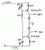
Hi pothound,
Okay, see the browse button at the bottom just above where the blue ends? Click on the "browse" button. Navigate your computer hard drive and find the file you want to post. Read the valid file extensions below for allowed file names.
This is a rough guide for you .........
The component values are rough guides. I used 1 W zeners and 1/2 W resistors.
-Chris
Attachments
- Status
- Not open for further replies.
- Home
- Amplifiers
- Solid State
- counterpoint sa100 headaches