Hi Guys,
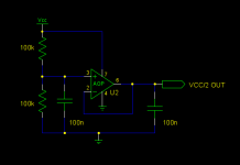
I am trying to understand some preamplifier designs, and I am confused about two different configurations in Non Inverting AC Coupled amplifiers. I don't know how to say it in words, so please take a look at the schematic image and give me some light. Thanks in regards.
Frank.
I am trying to understand some preamplifier designs, and I am confused about two different configurations in Non Inverting AC Coupled amplifiers. I don't know how to say it in words, so please take a look at the schematic image and give me some light. Thanks in regards.
Frank.
Attachments

Neither. VCC2 is ground which is the centre voltage. It is usual to have + - 15Volts as the supply. The non inverting input is tied to ground and the inverting input is AC coupled to ground, the two resistors make up the gain and the capacitor blocks DC to stop any offset issues.
I am trying to understand some preamplifier designs, and I am confused about
two different configurations in Non Inverting AC Coupled amplifiers.
Both will work. There may be less of a turn on/off transient with the nfb capacitor connected to Vcc/2.
Last edited:
Both will work.
And to answer the question in red, because you have a capacitor between inverting input and VCC/2 or Gnd, it doesn't matter what is the DC voltage at the other side of the capacitor.
And to answer the question in red, because you have a capacitor between inverting input and VCC/2 or Gnd, it doesn't matter what is the DC voltage at the other side of the capacitor.
Many thanks, Rayma and Wwenze. Now that i know that both will work, do you have any suggestion about which one is better? or are they completely equivalent?
Many thanks, Rayma and Wwenze. Now that i know that both will work, do you have
any suggestion about which one is better? or are they completely equivalent?
AC wise, they are equivalent if Vcc/2 has a low source impedance.
Check the output transient at turn-on and turn-off. If it is too much when the cap is directly grounded,
then connect the capacitor to the Vcc/2 point to minimize it.
Use a nonpolar capacitor if it is connected to Vcc/2, since then it will see both polarities of output voltage.
Last edited:
Vcc/2 is probably obtained by halving Vcc using two resistors of equal values, the one connected to ground being decoupled by an electrolytic cap.
However Vcc/2 may still contain some rubbish from Vcc.
The circuit on the right is much better to reject it.
The connection of the bottom of the resistor and the bottom of the cap should be very short and made before the connection using one track only to the circuit delivering Vcc/2.
However Vcc/2 may still contain some rubbish from Vcc.
The circuit on the right is much better to reject it.
The connection of the bottom of the resistor and the bottom of the cap should be very short and made before the connection using one track only to the circuit delivering Vcc/2.
Posts #3/5/7 are correct and have a point, for different reasons, to return NFB or consider Vcc/2 as audio ground, all based on "it may have some imperfections" .
For the very same reason I avoid that: I design and make Guitar amps, which involve very high gain, switching channels, etc. , and ground must be *perfect* , can never ever consider a cheesy 100uFx25V capacitor as *zero* ohms, by any means.
So I only trust real ground, not the virtual version.
Have had lots of problems with signal bleed, or even motorboating, if not respecting so.
IF Vcc/2 is hummy/noisy (which it may very well be) , ok .... clean it !! 🙂
Another advantage of using real ground is that standard electrolytics work very well, no need for bipolars.
Note that the non-inverting input is connected to Vcc/2.
This will affect the answer of "which is less noisy: connect inverting input to ground or Vcc/2"
This will affect the answer of "which is less noisy: connect inverting input to ground or Vcc/2"
Guys, many thanks for your answers. You are very wise. I will try the real ground version with electrolytic cap and I will buffer the virtual ground using another opamp.
Thanks,
Frank.
Thanks,
Frank.
Vcc/2 must be absolutely clean. Careless implementation will inject power supply noise directly into the high impedance + input.
I built some single supply line level circuits. I used a TLE2426 to bias the chips. I did not connect any signal ground to the "virtual ground." I isolated the 2426 with a series resistor (bigger resistor = more isolation) and filtering capacitor to ground. All signal grounds went to the - of the power supply. It works so well that you can use a laptop power supply to power it with no audible noise being injected.
My scheme uses the first circuit. All signal grounds go to the "real ground." In theory this leaves a little performance on the table (noise and distortion) but in the real world it is far more robust and practical.
I experimented with single supply line level op amp circuits and this was the result of my research. I achieved my goal of practical, low noise, low distortion circuits. I recommend that you try different ideas and come to your own conclusions.
Thanks Fast Eddie,
I will generate the vcc/2 with an opAmp and I will use it ONLY for the input bias. All other grounds will be to real ground. It is a lot more practical and as you pointed seems to be the best approach.
I will generate the vcc/2 with an opAmp and I will use it ONLY for the input bias. All other grounds will be to real ground. It is a lot more practical and as you pointed seems to be the best approach.
That will work. Caveat is that an op amp might not like to drive a capacitive load; you might need a series isolation resistor. Both input and output of the virtual ground must be shunted to the "real" ground with appropriate value electrolytic capacitors. Ceramic capacitors should go on the input and output of the op amp. I suggest 0.1 uF. If you're not careful about all this, you will introduce noise.
Remember to isolate the op amp positive power supply lead with a local R/C network. One resistor (not too critical; 4.7 K should work for biasing a couple of 5532s for instance) and one capacitor will do.
Remember to isolate the op amp positive power supply lead with a local R/C network. One resistor (not too critical; 4.7 K should work for biasing a couple of 5532s for instance) and one capacitor will do.
Refering the -input to the same Vcc/2 is beneficial for rejection,Vcc/2 must be absolutely clean. Careless implementation will inject power supply noise directly into the high impedance + input.
thanks to what is called the input common mode rejection.
Some Linsley-Hood power amps with capacitive coupling output did that.
Last edited:
Yes, and the loop area must be kept small.Refering the -input to the same Vcc/2 is beneficial for rejection,
thanks to what is called the input common mode rejection............
virtual ground circuit
Thanks Guys,
Taking into account your suggestions, I will use the following circuit to provide Vcc/2. And I will experiment referencing the inverting input to GND or to Vcc/2, if both works I will just select the better in terms of noise.
Thanks Guys,
Taking into account your suggestions, I will use the following circuit to provide Vcc/2. And I will experiment referencing the inverting input to GND or to Vcc/2, if both works I will just select the better in terms of noise.
Attachments
Refering the -input to the same Vcc/2 is beneficial for rejection,
thanks to what is called the input common mode rejection.
Some Linsley-Hood power amps with capacitive coupling output did that.
You're correct.
Vcc/2 is tied to the "real ground" through a shunting capacitor. The AC and DC currents don't follow all the same paths. AC performance is paramount to audio circuits; DC precision is secondary.
So my configuration does not have optimum DC common mode rejection, but it does have optimum AC common mode rejection.
Asking virtual grounds to do extra heavy lifting is also asking for them to introduce distortion. My setup does not rely on the virtual ground to do anything with the AC signal. This is a simplification with no consequence for this circuit. Also, input/output jacks do not have to be isolated from the chassis. Remember, it works off a wall wart or laptop supply.
There's more than one "right" way and this configuration is not optimal for all circuits.
- Status
- Not open for further replies.
- Home
- Amplifiers
- Chip Amps
- Correct Op Amp Single supply non inverting Amplifier