Hi All,
I have a Yamaha CDX-630E CD player (Based on Sony CDP-207ESD CD player) which I would like to "convert" it so I can use it as a Dac.
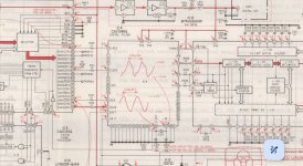
My plan is to connect an input board (DIR9001 based) directly to the TDA1541A chip or to the digital filter if possible after disabling the CD function.
I have a few questions and I'll appreciate your assistance:
1. The DIR9001 input board has I2S output (MCLK, BCLK, LRCK, DATA), assuming I wish to use the digital filter can the I2S be connected directly to the IC4 ? where do I need to connect the MCLK output in the IC4 chip?
2. I noticed that in this Yamaha CD player there are 1K resistors before the Dac inputs, in other CD players the resistors values vary(some use 100r some use 390r), what is the effect of using 1K resistor in comparison to a lower value resistors?
3. I noticed that in the CD player's output stage there is not low pass filter, just an I/U conversion stage, isn't it an issue?
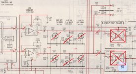
4. My plan is to replace C325/C326 electrolytics (which is part of the output's high pass filtering) with PP or other type of non electrolytic caps, if my calculations are correct then the 47uF C325 and 330K R307 form a very low high pass filtering of 0.01hz -3db, is that really necessary ? can I replace the 47uF cap with lets say a 3uF cap?
5. What is the purpose of R319, R327, R309 ? are they necessary or should I bypass them?
Thanks in advance.
I have a Yamaha CDX-630E CD player (Based on Sony CDP-207ESD CD player) which I would like to "convert" it so I can use it as a Dac.
My plan is to connect an input board (DIR9001 based) directly to the TDA1541A chip or to the digital filter if possible after disabling the CD function.
I have a few questions and I'll appreciate your assistance:
1. The DIR9001 input board has I2S output (MCLK, BCLK, LRCK, DATA), assuming I wish to use the digital filter can the I2S be connected directly to the IC4 ? where do I need to connect the MCLK output in the IC4 chip?
2. I noticed that in this Yamaha CD player there are 1K resistors before the Dac inputs, in other CD players the resistors values vary(some use 100r some use 390r), what is the effect of using 1K resistor in comparison to a lower value resistors?
3. I noticed that in the CD player's output stage there is not low pass filter, just an I/U conversion stage, isn't it an issue?
4. My plan is to replace C325/C326 electrolytics (which is part of the output's high pass filtering) with PP or other type of non electrolytic caps, if my calculations are correct then the 47uF C325 and 330K R307 form a very low high pass filtering of 0.01hz -3db, is that really necessary ? can I replace the 47uF cap with lets say a 3uF cap?
5. What is the purpose of R319, R327, R309 ? are they necessary or should I bypass them?
Thanks in advance.
Attachments
Looking at the datasheet, https://pdf1.alldatasheet.com/datasheet-pdf/view/120105/SONY/CXD1088AQ.html , the inputs are not necessarily compatible with the 3.3 V of the DIR9001; you need luck or 3.3 V to 5 V level converters for the high levels to be interpreted as high levels.
The timing diagram seems to indicate that the input format is MSB first, right justified rather than I2S. The DIR9001 can work in that format as well, but I don't know if your DIR9001 board can.
It's not clear to me whether the digital filter chip requires its 16.9344 MHz crystal clock to be an exact multiple of the sample rate.
#1 No idea.
#2 The resistors isolate the outputs of the previous Digital Filter chip and may help with supressing any ringing or artefacts caused by stray and/or junction capacitance of the following stage. The optimum value depends on the impedance seen by the DAC at its inputs.
#3 Not an issue. The CD format has precisely defined bandwidth limits.
#4 Its up to you. You have to include the input impedance of the headphone amp and any external equipment connected to the line output sockets in your calculations. I would stick with the recommended values.
#5 R309 and R327 are required for the mute circuitry to operate correctly and also for the de emphasis function to work. If you remove these and/or Q12 then the frequency response will be wrong on discs with pre emphasis used in their mastering. R319 isolates the output stage from such things as stray capacitance such as in RCA leads.

Looking at the datasheet, https://pdf1.alldatasheet.com/datasheet-pdf/view/120105/SONY/CXD1088AQ.html , the inputs are not necessarily compatible with the 3.3 V of the DIR9001; you need luck or 3.3 V to 5 V level converters for the high levels to be interpreted as high levels.
The timing diagram seems to indicate that the input format is MSB first, right justified rather than I2S. The DIR9001 can work in that format as well, but I don't know if your DIR9001 board can.
It's not clear to me whether the digital filter chip requires its 16.9344 MHz crystal clock to be an exact multiple of the sample rate.
Thanks MarcelvdG,
I've already connected the DIR9001 input board directly to the TDA1541A chip and it was working perfectly, I'm wondering if it will also work connecting it to the digital filter and if there is any benefit in doing so, what do you think?
Thanks Mooly,
Just to clarify, I'm not going to use the CD player as a CD player anymore, my intention is to omit the CD function completely and just use it's DAC section as a DAC for a streamer.
As for "#2 The resistors isolate the outputs of the previous Digital Filter chip and may help with supressing any ringing or artefacts caused by stray and/or junction capacitance of the following stage. The optimum value depends on the impedance seen by the DAC at its inputs."
How can I know/calculate that?
As for "#3 Not an issue. The CD format has precisely defined bandwidth limits."
I plan to connect the DAC to a streamer so the bandwidth might not be limited.
As for "#4 Its up to you. You have to include the input impedance of the headphone amp and any external equipment connected to the line output sockets in your calculations. I would stick with the recommended values."
I'll omit the headphones amp completely.
As for "#5 R309 and R327 are required for the mute circuitry to operate correctly and also for the de emphasis function to work. If you remove these and/or Q12 then the frequency response will be wrong on discs with pre emphasis used in their mastering. R319 isolates the output stage from such things as stray capacitance such as in RCA leads."
The mute circuitry will be removed, in this case wouldn't it be better to bypass R309 and R327 as well ?
Do I need the de emphasis function to work if I won't use the CD player as a CD player but as a DAC only ?
Thanks
You can't simply because you don't know the impedances and capacitance involved. If you start altering the resistors you are really saying you know better than the designers. In practice they are probably not that critical.As for "#2 The resistors isolate the outputs of the previous Digital Filter chip and may help with supressing any ringing or artefacts caused by stray and/or junction capacitance of the following stage. The optimum value depends on the impedance seen by the DAC at its inputs."
How can I know/calculate that?
You have to decide then what lower limit you want and scale the cap and resistor accordingly. Again in practice, this will be a non issue.As for "#3 Not an issue. The CD format has precisely defined bandwidth limits."
I plan to connect the DAC to a streamer so the bandwidth might not be limited.
You should always keep some series resistance from the opamp output to the output socket but it needs only be a few tens of ohms to keep the opamp happy. So you could use something like a single 47 ohm.The mute circuitry will be removed, in this case wouldn't it be better to bypass R309 and R327 as well ?
Do I need the de emphasis function to work if I won't use the CD player as a CD player but as a DAC only ?
I'm guessing not if you use it as a streamer.
Thank you Mooly.
As for "You should always keep some series resistance from the opamp output to the output socket but it needs only be a few tens of ohms to keep the opamp happy. So you could use something like a single 47 ohm."
So basically I can leave R319 and R320 and omit all the other resistors after the opamp output, correct?
1. The DIR9001 MCLK will connect to X IN on the CXD1088Q but the snag will be bit clock. For the DIR9001 it is 64Fs and for the CXD1088Q it is 48Fs.1. The DIR9001 input board has I2S output (MCLK, BCLK, LRCK, DATA), assuming I wish to use the digital filter can the I2S be connected directly to the IC4 ? where do I need to connect the MCLK output in the IC4 chip?
3. I noticed that in the CD player's output stage there is not low pass filter, just an I/U conversion stage, isn't it an issue?
3. Connecting directly to the TDA1541A means going from 4Fs to Fs and might require the low pass filter to be scaled accordingly. OTOH, if the sound is to your liking as is.......
Link out rather than omit but yes you can do that. Their value will determine the output impedance.So basically I can leave R319 and R320 and omit all the other resistors after the opamp output, correct?
Yes, sorry I meant what you've mentioned🙂
Would it be better to use lower value resistor than R319/320 680r?
Would it be better to use lower value resistor than R319/320 680r?
I kind of "rely" on my amplifier's input stage (currently Rega Elex r) to cut the ultra high frequencies, as far as I know all the "new" amplifiers have a low pass filter in their input stage, am I wrong?1. The DIR9001 MCLK will connect to X IN on the CXD1088Q but the snag will be bit clock. For the DIR9001 it is 64Fs and for the CXD1088Q it is 48Fs.
3. Connecting directly to the TDA1541A means going from 4Fs to Fs and might require the low pass filter to be scaled accordingly. OTOH, if the sound is to your liking as is.......
At Fs the images are much much lower. Low enough to be an issue. There is a thread by Abraxalito that covers this and the evolving efforts to ameliorate said effects.
There isn't really a better or best value as it 100% depends on what you connect it to. 680R is a perfectly good option but if you wish you can go a lot lower. You can also go a lot higher if you are concerned about ultra high frequencies but again, how high depends on what you feeding it into.Would it be better to use ower value resistor than R319/320 680r?

It looks like some kind of jumper. No idea why some models have jumpers and others ordinary traces.
They are CP's or 'circuit protectors'. The marked value is to be multiplied by forty to get the current in milliamps and so an N25 is a 1Amp slow blow. They were very common in lots of consumer equipment back in the 80's and 90's.

Maybe a little late to the subject but if you are using a streamer why not use a really well implemented USB to i2s board. The Amanero is ok and I really like the DIYINHK units that have reclockers and isolators onboard. You will have to implement a VERY good powersupply to get everything out of them but it will modernize your DAC section.
I have been playing with TDA1541 cd players. Building some dac's / modding cd players. The i/v output circuit on this player is very basic. Not saying it wont work. As it worked fine as a CD player. There is often a little more in the way of passive filtering on a TDA1541 output and a 2nd stage of op amp to drive the output. I guess with over sampling from the digital filter any digital noise would be way above human hearing.
As dht 4 me says, I use a USB to i2s board.
As dht 4 me says, I use a USB to i2s board.
Thank you but my streamer have only optical output.Maybe a little late to the subject but if you are using a streamer why not use a really well implemented USB to i2s board. The Amanero is ok and I really like the DIYINHK units that have reclockers and isolators onboard. You will have to implement a VERY good powersupply to get everything out of them but it will modernize your DAC section.
I had a DIYINHK USB to I2S board before for different usage and it was great.....until it died for no reason🙂
- Home
- Source & Line
- Digital Source
- Converting Yamaha CDX-630E CD player to a DAC