Question on using headphones in a SET amplifier.
In the amplifiers that I have built so far, two low-wattage SET designs, I have paralleled a resistor on the OPT headphone output such that the tube sees its ideal load, typically an 8.2ohm resistor across an 8ohm secondary winding.
However, I am aware of some builders who use speaker-rated OPT specifically for headphone amplifiers (no speaker outputs) and do not use a paralleled resistor.
As such, the reflected load to the tube is enormous. For example, with a 5K:8ohm OPT and 300ohm load, the reflected primary impedance would be 187.5K, although that is likely innaccurate due to real-world transformer limitations.
This high reflected load would be a near-horizontal load line for the output tube. With all of that being said...
Given the output tube is typically biased near max plate dissipation, is there any concern for the dissipation going over max rating on the positive voltage peaks? I have heard/read mixed takes on this, one being that the tube can safely make excursions past max plate dissipation on transients, others have said it is harmful.
What are the disadvantages of connecting headphones directly to the OPT vs. paralleling a resistor? Power output into the headphones would be quite low given the high reflected primary impedance, so I take it damaging the headphones is not a concern.
Thanks for explaining.
Last edited:
On my valve amps I always add a resistor across output in case amp is powered without speaker/headphones.
For 8 ohms even 100R helps. At least it puts some sort of load on the transformer.
For 8 ohms even 100R helps. At least it puts some sort of load on the transformer.
On my valve amps I always add a resistor across output in case amp is powered without speaker/headphones.
For 8 ohms even 100R helps. At least it puts some sort of load on the transformer.
Thanks Nigel, I do the same, I put a 470R resistor across the secondaries of my amps to protect from open circuits.
There is no one singular answer. Nothing simple about it.
Single Ended, right?
But which output tube?
Triode; Triode Wired Beam Power; Triode wired Pentode; Screen connected to screen tap on the output transformer (True UL, or the wrong % tap for the Beam Power/Pentode in use)?
No Global Negative Feedback?
No Schade or Cathode Negative Feedback?
Global Negative Feedback?
Open Loop gain, versus closed loop gain?
What is the stability of the amp with negative feedback, and no load?
Will you ever turn the volume up so that the amp is anywhere near clipping?
Will the input connector ground come free, and the center pin stay connected, so that hum is output at the full power level?
Finally, what happens to that same amplifier if the volume is turned up, and the loudspeaker is mistakenly or accidentally disconnected?
With all of the above, it is better to be safe than sorry . . .
Use a proper terminating resistor.
One more factor:
Most headsets Do have relatively constant impedance across the audio frequency band.
But . . .
Most output transformers do Not have constant impedance at the primary, when the secondary is either not loaded, or only slightly loaded.
If that amplifier does not have Global Negative Feedback, then both the Low Frequencies, and often the High Frequencies will be attenuated.
Why?
The output tube does Not "see" the load when the secondary is unloaded, or when it is lightly loaded.
What the output tube Does "see" is the low impedance at low frequencies due to the primary inductance;
and it "sees" the low impedance at high frequencies due to the distributed capacitance of the primary windings.
At mid frequencies, the tube sees a very high impedance, so the amplitude goes up there, and down at low and high frequencies.
Given 5k Ohm to 8 Ohm output tranformer that has a 470 Ohm resistor across the 8 Ohm tap to Common tap,
is just like a (5k/8) x 470 Ohm resistor across the primary.
That is equivalent to putting a 293,750 Ohm resistor across the 5k primary . . . close to Zero Effect.
Conclusion:
Be safe, terminate the output.
Get better frequency response, terminate the output.
"You should make things as simple as possible, but no simpler" Albert Einstein.
Last edited:
Thanks 6A3, let me be more specific. First, leaving the secondary unloaded is not my practice, I load the secondary with a 470ohm resistor. Then on the headphone output (accesible with a switch), I also place an 8.2ohm resistor, such that the parallel load of the 470ohm + 8ohm + headphone is approximately 8ohm.
I ask the question as I have seen someone use this headphone output with a parallel resistance to protect from open circuits, but no resistor on the headphone output. So their hypothetical setup is a 470ohm resistor in parallel with a 300ohm headphone only. For the example, we can use my 6A5 amplifier which has a 3.3K:8ohm OPT (Lundahl LL1620 60mA 60H) with no negative feedback, cathode biased.
I took a series of measurements examining the effect of changing the headphone output resistance and removing it entirely. I measured THD and frequency response with 9.1ohm, 16.2ohm, and no resistance on the headphone output.
So the setup went OPT secondary in parallel with 470ohm, in parallel with 9.1ohm/16ohm/no resistance, in parallel with 300ohm dummy load.
The frequency response across all three measurements was identical, flat from 20Hz-17kHz and down about 1.6dB at 20kHz. However, the distortion profile did change, with second harmonic significantly reduced in the "no resistance" scenario. The measurements below are at 0.5Vrms output into 300ohms.
9.1ohm: 0.33% THD, H2 at -54dBFS, H3 -80dBFS
16ohm: 0.17% THD, H2 at -60dBFS, H3 -80dBFS
No resistance: 0.077% THD, H2 at -65dBFS, H3 -80dBFS
With no resistance, the secondary load is 470ohm in parallel with 300ohm, so approximately 183ohm. The reflected primary resistance would then be 187*(3300/8) = 75K plate load for the output tube.
So my thinking is the reduced second harmonic is a result of the "flat" load line for the output tube. I preferred the sound of the 9.1ohm resistance with higher distortion, but I am curious, if I had left the setup this way with the output tube swinging above the max plate dissipation on the positive voltage peaks, as would be the case for a 75K load line, would this cause a problem?
I hope this makes it more clear, I was not suggesting the secondary be left completely unloaded.
L0rdGwyn,
Good to see your response; and the work you did measuring distortion at different loading impedances.
I believe most lundahl transformers are rated for 1kV or 2kV from primary to secondary, and/or to the laminations.
I do not remember the voltage ratings of the primary (end to end). I think that rating is more related to saturation levels at 30 Hz, and not a voltage breakdown rating.
But we do know that 1/2 of the primary is wound over one air gap, and the other primary 1/2 is wound over the other air gap;
and likewise with 1/2 of the secondary over one air gap, and the other 1/2 of the secondary over the other air gap.
As to using the amplifier safely with very light loading . . .
You have the best safety scenario possible for an SE amplifier that uses the output tube plate to drive the primary (a cathode follower output might be even better, depending on other factors).
One factor is with no negative feedback, there are no stability problems, it is very unlikely to become a full power oscillator.
The other good factor is that your 6A5 is a triode, with a u = 4.2.
Suppose you never have too large of a signal voltage from the driver, such that the 6A5 not go into complete cutoff. In that case, the maximum voltage swing the plate will go above B+ is: Grid Bias Voltage x 4.2. Given a -45V grid to cathode bias voltage, that is 45 x 4.2 = 189V swing above the quiescent B+ level.
However, if the driver tube ever runs the 6A5 fully into cutoff, then the primary of the transformer can swing many times the B+ voltage; until the tube arcs, or the primary arcs, or both.
You should also be using and applying that amplifier to either drive some near-field speakers at the computer or the bedrooom;
or to drive some very efficient speakers in the living room.
Just remember to be careful not to let the speaker connections come off.
What sometimes happens, when someone moves an amplifier from one room to another, or from one setup to another, they do not get the speakers connected. Then, they turn the volume up all the way (the most common mode of "troubleshooting" for that scenario). And that has the potential to cause the amplifier to arc over.
Happy listening!
Last edited:
> concern for the dissipation going over max rating on the positive voltage peaks?
The plate has a thermal time-constant of many seconds. We can generally "average over a whole audio cycle".
Yes, the THD tends to go down as load goes up. Good bass extension depends on a low-resistance tube relative to OT inductance.
The plate has a thermal time-constant of many seconds. We can generally "average over a whole audio cycle".
Yes, the THD tends to go down as load goes up. Good bass extension depends on a low-resistance tube relative to OT inductance.
Last edited:
My discussion for an amplifier that was unloaded "breaking" was not because of dissipation limits.
Instead, we are talking about possibly going over the voltage limits of the tube and the output transformer.
Try an SE pentode amp with no negative feedback, and no loading on the output transformer, and then drive it with a very fast rise time signal until the output tube control grid, G1 is so negative that it is just shy of arcing. At that point, the plate will go so positive that it will be several times B+.
And do not try this in a real humid environment.
I would be surprised if normal music did this to the amp, but an over-zealous tester with a fast rise signal generator may try it.
Ever hear of an ignition coil?
just sayin'
I will not try that with any of my amplifiers.
Last edited:
> My discussion for an amplifier that was unloaded "breaking" was not because of dissipation limits.
I was not replying to your remarks.
I was not replying to your remarks.
PRR,
I am sorry, I misread your comment.
It is getting late, I am tired, and I did not know what Post # you were referring to.
I am sorry, I misread your comment.
It is getting late, I am tired, and I did not know what Post # you were referring to.
Just a note on nomenclature here - a high resistance is a light load, a low resistance is a heavy load - its the conductance, not the resistance that determines the quality of a load - well to be fully general its the admittance (reciprocal of impedance) since reactive loads also matter.However, I am aware of some builders who use speaker-rated OPT specifically for headphone amplifiers (no speaker outputs) and do not use a paralleled resistor.
As such, the reflected load to the tube is enormous. For example, with a 5K:8ohm OPT and 300ohm load, the reflected primary impedance would be 187.5K, although that is likely innaccurate due to real-world transformer limitations.
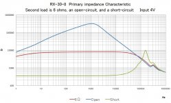
I think you will find that the limitations are significant. I've attached some measurements of a transformer shorted, resisitvely loaded, and open.As such, the reflected load to the tube is enormous. For example, with a 5K:8ohm OPT and 300ohm load, the reflected primary impedance would be 187.5K, although that is likely innaccurate due to real-world transformer limitations.
If you use a triode and load it with a transformer that is at least 3x Rp, then the changes in reflected impedance don't make much difference in terms of gain/frequency response, but as you have noticed THD will go down where the reflected load has gone up.
For the amp you have built, a resistor is not required across the output transformer terminals. The maximum possible voltage swing is well limited by the low mu of the triodes you are using.
Attachments
audiowise,
1. Yes, I agree.
His triode amplifier in question will not arc over even if it is unterminated.
I listed it's approximate limits of peak plate voltage under normal drive conditions
(u x bias Voltage) + (B+ Voltage). See Post #6.
Only when driven with a fast rise generator, and only if the driver has a fast enough rise time and large enough voltage excursion, might the output tube and/or output transformer arc over.
But it can never happen when driven by a Redbook CD player (which are all bandwidth limited, and are all rise time limited).
2. Thanks for the graph!
That is a nice illustration of some transformer characteristics:
The open condition shows the resonance of the primary's inductance with the primary's distributed capacitance.
The shorted condition shows the resonance caused by the leakage reactance (non coupling of the primary to the secondary), resonating with the distributed capacitance.
I also noticed the curves all show a small additional effect from about 25kHz to 30kHz.
I know, I am "preaching to the choir".
But there are others here who are not in the choir.
Question:
What was the model of the transformer you tested?
Question:
Did you ground one end of the secondary, relative to AC ground of one end of the primary, when you did the 3 tests?
Last edited:
I didn't make that picture, I just saw it and realized that it illustrated something I've explained periodically over the years.
Thanks for the picture anyway.
It really is good for some others to see.
It reminds me of when I had a 10Hz to 4 GHz $50,000 Vector Network Analyzer at work.
Among other things, I tested interstage transformers, output transformers, speaker cable, vacuum tube amplifiers into a non-inductive resistor;
and electrical throughput of amplifier + loudspeaker (The phase and frequency response of the amplifier with a speaker load; no Acoustic testing).
It's nice to have such tools available that you don't have to pay for. Thankfully test gear seems to get a little less expensive every year.
Thank you 6A3sUMMER, PRR, Mark Tillotson, and audiowize for your thorough responses.
Unfortunately I have been very busy at work and haven't had the time to go through them in detail, rest assured I will over the next few days. This forum has been invaluable for someone still new to DIY tube audio, very much appreciated.
Unfortunately I have been very busy at work and haven't had the time to go through them in detail, rest assured I will over the next few days. This forum has been invaluable for someone still new to DIY tube audio, very much appreciated.
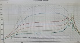
I agree Audiowize posted graph is interesting and I've seen that around before.
Here attached is my own impedance investigation of a single ended OPT in my possession.
It shows the effect of loading the secondary with 1x, 2x and 4x the intended load. I didnt go as far as 10 times, as the restriction on frequency response is already very apparent.
Here attached is my own impedance investigation of a single ended OPT in my possession.
It shows the effect of loading the secondary with 1x, 2x and 4x the intended load. I didnt go as far as 10 times, as the restriction on frequency response is already very apparent.
Attachments
Last edited:
- Home
- Amplifiers
- Tubes / Valves
- Connecting Headphones Directly to OPT in SET